Session7. Packaging & Board Design
(Mon Mar 9) *Toward the Finish line alongside classmates and AI tools.
-
My Final Code Link: Coloring Wing - hello_morse
-
My Final Code: hello_morse.v
// ============================================================================
// LED Color Buzzer Morse Beacon - Kyunghee Yoo - Microelectronics 2026
// hello_morse.v -Lint
// ============================================================================
`timescale 1ns/1ps
module hello_morse #(
parameter integer CLK_FREQ = 50_000_000, // Clock speed in Hz
parameter integer NUM_LEDS = 8 // Number of LEDs in the strip
)(
input wire clk,
input wire rst_n,
input wire btn_color, // Button to cycle colors
output wire led_data, // Data output to WS2812 strip
output wire buzzer_pwm // 600 Hz piezo buzzer output
);
// ========================================================================
// MESSAGE MEMORY
// ========================================================================
localparam integer MSG_LEN = 9;
localparam integer CHAR_IDX_W = (MSG_LEN <= 1) ? 1 : $clog2(MSG_LEN);
localparam [CHAR_IDX_W-1:0] LAST_CHAR = MSG_LEN - 1;
localparam [CHAR_IDX_W-1:0] ONE_CHAR = 1;
localparam [CHAR_IDX_W-1:0] TWO_CHARS = 2;
localparam [CHAR_IDX_W-1:0] NEXT_LAST_CHAR = MSG_LEN - 2;
reg [7:0] message [0:MSG_LEN-1];
initial begin
message[0] = "H"; // ....
message[1] = "E"; // .
message[2] = "R"; // .-.
message[3] = "E"; // .
message[4] = " "; // word gap
message[5] = "I"; // ..
message[6] = " "; // word gap
message[7] = "A"; // .-
message[8] = "M"; // --
end
// ========================================================================
// MORSE CODE LOOKUP TABLE
// Format: {length[3:0], pattern[7:0]}
// Pattern is sent LSB first. 0 = dot, 1 = dash.
// ========================================================================
function [11:0] get_morse;
input [7:0] ch;
begin
case (ch)
"A": get_morse = {4'd2, 8'b00000010}; // .-
"B": get_morse = {4'd4, 8'b00000001}; // -...
"C": get_morse = {4'd4, 8'b00000101}; // -.-.
"D": get_morse = {4'd3, 8'b00000001}; // -..
"E": get_morse = {4'd1, 8'b00000000}; // .
"F": get_morse = {4'd4, 8'b00000100}; // ..-.
"G": get_morse = {4'd3, 8'b00000011}; // --.
"H": get_morse = {4'd4, 8'b00000000}; // ....
"I": get_morse = {4'd2, 8'b00000000}; // ..
"J": get_morse = {4'd4, 8'b00001110}; // .---
"K": get_morse = {4'd3, 8'b00000101}; // -.-
"L": get_morse = {4'd4, 8'b00000010}; // .-..
"M": get_morse = {4'd2, 8'b00000011}; // --
"N": get_morse = {4'd2, 8'b00000001}; // -.
"O": get_morse = {4'd3, 8'b00000111}; // ---
"P": get_morse = {4'd4, 8'b00000110}; // .--.
"Q": get_morse = {4'd4, 8'b00001011}; // --.-
"R": get_morse = {4'd3, 8'b00000010}; // .-.
"S": get_morse = {4'd3, 8'b00000000}; // ...
"T": get_morse = {4'd1, 8'b00000001}; // -
"U": get_morse = {4'd3, 8'b00000100}; // ..-
"V": get_morse = {4'd4, 8'b00001000}; // ...-
"W": get_morse = {4'd3, 8'b00000110}; // .--
"X": get_morse = {4'd4, 8'b00001001}; // -..-
"Y": get_morse = {4'd4, 8'b00001101}; // -.--
"Z": get_morse = {4'd4, 8'b00000011}; // --..
" ": get_morse = {4'd0, 8'b00000000}; // word gap marker
default: get_morse = {4'd0, 8'b00000000};
endcase
end
endfunction
// ========================================================================
// MORSE TIMING
// ========================================================================
localparam integer UNIT_TIME = CLK_FREQ / 10; // 100 ms per unit
localparam integer DOT_TIME = UNIT_TIME;
localparam integer DASH_TIME = UNIT_TIME * 3;
localparam integer SYM_GAP = UNIT_TIME;
localparam integer CHAR_GAP = UNIT_TIME * 3;
localparam integer WORD_GAP = UNIT_TIME * 7;
// ========================================================================
// BUZZER CONFIGURATION
// ========================================================================
localparam integer BUZZER_FREQ = 600;
localparam integer PWM_PERIOD = CLK_FREQ / BUZZER_FREQ;
reg [31:0] buzzer_counter;
reg buzzer_tone;
// ========================================================================
// BUTTON / COLOR CONTROL
// ========================================================================
wire btn_pressed;
debounce #(
.CLK_FREQ(CLK_FREQ)
) debounce_inst (
.clk(clk),
.rst_n(rst_n),
.btn_raw(btn_color),
.btn_pressed(btn_pressed)
);
reg [1:0] color_mode;
always @(posedge clk or negedge rst_n) begin
if (!rst_n)
color_mode <= 2'd0;
else if (btn_pressed)
color_mode <= color_mode + 2'd1;
end
reg [23:0] on_color;
reg [23:0] off_color;
always @(*) begin
case (color_mode)
2'd0: begin on_color = 24'h00FF00; off_color = 24'h000000; end // Red in GRB
2'd1: begin on_color = 24'hFF0000; off_color = 24'h000000; end // Green in GRB
2'd2: begin on_color = 24'h0000FF; off_color = 24'h000000; end // Blue in GRB
2'd3: begin on_color = 24'hFFFFFF; off_color = 24'h050500; end // White / dim off
default: begin on_color = 24'h00FF00; off_color = 24'h000000; end
endcase
end
// ========================================================================
// MORSE CODE STATE MACHINE
// ========================================================================
localparam [2:0] MS_LOAD = 3'd0;
localparam [2:0] MS_SYMBOL = 3'd1;
localparam [2:0] MS_SYM_GAP = 3'd2;
localparam [2:0] MS_CHAR_GAP = 3'd3;
localparam [2:0] MS_WORD_GAP = 3'd4;
localparam [2:0] MS_RESTART = 3'd5;
reg [2:0] morse_state;
reg [CHAR_IDX_W-1:0] char_idx;
reg [11:0] morse_data;
reg [3:0] symbol_idx;
reg [31:0] morse_timer;
reg leds_on;
wire [3:0] morse_len = morse_data[11:8];
wire is_dash = morse_data[symbol_idx];
wire [11:0] curr_char_morse = get_morse(message[char_idx]);
wire [3:0] curr_char_len = curr_char_morse[11:8];
wire curr_is_space = (message[char_idx] == " ");
wire next_char_is_space =
(char_idx < LAST_CHAR) && (message[char_idx + ONE_CHAR] == " ");
always @(posedge clk or negedge rst_n) begin
if (!rst_n) begin
morse_state <= MS_LOAD;
char_idx <= {CHAR_IDX_W{1'b0}};
morse_data <= 12'd0;
symbol_idx <= 4'd0;
morse_timer <= 32'd0;
leds_on <= 1'b0;
end else begin
case (morse_state)
MS_LOAD: begin
leds_on <= 1'b0;
morse_data <= curr_char_morse;
symbol_idx <= 4'd0;
morse_timer <= 32'd0;
if (curr_is_space || (curr_char_len == 4'd0))
morse_state <= MS_WORD_GAP;
else
morse_state <= MS_SYMBOL;
end
MS_SYMBOL: begin
leds_on <= 1'b1;
morse_timer <= morse_timer + 32'd1;
if (( is_dash && (morse_timer >= DASH_TIME - 1)) ||
(!is_dash && (morse_timer >= DOT_TIME - 1))) begin
leds_on <= 1'b0;
morse_timer <= 32'd0;
if ((symbol_idx + 4'd1) >= {1'b0, morse_len}) begin
if (char_idx >= LAST_CHAR)
morse_state <= MS_RESTART;
else if (next_char_is_space)
morse_state <= MS_WORD_GAP;
else
morse_state <= MS_CHAR_GAP;
end else begin
symbol_idx <= symbol_idx + 4'd1;
morse_state <= MS_SYM_GAP;
end
end
end
MS_SYM_GAP: begin
leds_on <= 1'b0;
morse_timer <= morse_timer + 32'd1;
if (morse_timer >= SYM_GAP - 1) begin
morse_timer <= 32'd0;
morse_state <= MS_SYMBOL;
end
end
MS_CHAR_GAP: begin
leds_on <= 1'b0;
morse_timer <= morse_timer + 32'd1;
if (morse_timer >= CHAR_GAP - 1) begin
morse_timer <= 32'd0;
char_idx <= char_idx + ONE_CHAR;
morse_state <= MS_LOAD;
end
end
MS_WORD_GAP: begin
leds_on <= 1'b0;
morse_timer <= morse_timer + 32'd1;
if (morse_timer >= WORD_GAP - 1) begin
morse_timer <= 32'd0;
if (curr_is_space) begin
if (char_idx >= LAST_CHAR) begin
morse_state <= MS_RESTART;
end else begin
char_idx <= char_idx + ONE_CHAR;
morse_state <= MS_LOAD;
end
end else begin
if (char_idx >= NEXT_LAST_CHAR) begin
morse_state <= MS_RESTART;
end else begin
char_idx <= char_idx + TWO_CHARS;
morse_state <= MS_LOAD;
end
end
end
end
MS_RESTART: begin
leds_on <= 1'b0;
morse_timer <= morse_timer + 32'd1;
if (morse_timer >= WORD_GAP - 1) begin
morse_timer <= 32'd0;
char_idx <= {CHAR_IDX_W{1'b0}};
morse_state <= MS_LOAD;
end
end
default: begin
morse_state <= MS_LOAD;
char_idx <= {CHAR_IDX_W{1'b0}};
morse_timer <= 32'd0;
leds_on <= 1'b0;
end
endcase
end
end
// ========================================================================
// BUZZER DRIVER - 600 HZ SQUARE WAVE
// ========================================================================
always @(posedge clk or negedge rst_n) begin
if (!rst_n) begin
buzzer_counter <= 32'd0;
buzzer_tone <= 1'b0;
end else begin
if (buzzer_counter >= (PWM_PERIOD / 2 - 1)) begin
buzzer_counter <= 32'd0;
buzzer_tone <= ~buzzer_tone;
end else begin
buzzer_counter <= buzzer_counter + 32'd1;
end
end
end
assign buzzer_pwm = leds_on ? buzzer_tone : 1'b0;
// ========================================================================
// WS2812 DRIVER
// ========================================================================
localparam [15:0] T0H = CLK_FREQ / 2_500_000; // 0.4 us
localparam [15:0] T0L = CLK_FREQ / 1_250_000; // 0.8 us
localparam [15:0] T1H = CLK_FREQ / 1_250_000; // 0.8 us
localparam [15:0] T1L = CLK_FREQ / 2_500_000; // 0.4 us
localparam [15:0] TRESET = CLK_FREQ / 20_000; // 50 us
localparam [1:0] WS_RESET = 2'd0;
localparam [1:0] WS_LOAD = 2'd1;
localparam [1:0] WS_HIGH = 2'd2;
localparam [1:0] WS_LOW = 2'd3;
localparam integer LED_IDX_W = (NUM_LEDS <= 1) ? 1 : $clog2(NUM_LEDS);
localparam [LED_IDX_W-1:0] LAST_LED = NUM_LEDS - 1;
reg [1:0] ws_state;
reg [LED_IDX_W-1:0] led_idx;
reg [4:0] bit_idx;
reg [23:0] pixel_data;
reg [15:0] timer;
reg data_out;
wire [23:0] current_color = leds_on ? on_color : off_color;
always @(posedge clk or negedge rst_n) begin
if (!rst_n) begin
ws_state <= WS_RESET;
led_idx <= {LED_IDX_W{1'b0}};
bit_idx <= 5'd0;
pixel_data <= 24'd0;
timer <= 16'd0;
data_out <= 1'b0;
end else begin
case (ws_state)
WS_RESET: begin
data_out <= 1'b0;
timer <= timer + 16'd1;
if (timer >= (TRESET - 16'd1)) begin
timer <= 16'd0;
led_idx <= {LED_IDX_W{1'b0}};
ws_state <= WS_LOAD;
end
end
WS_LOAD: begin
pixel_data <= current_color;
bit_idx <= 5'd23;
timer <= 16'd0;
ws_state <= WS_HIGH;
end
WS_HIGH: begin
data_out <= 1'b1;
timer <= timer + 16'd1;
if (pixel_data[bit_idx]) begin
if (timer >= (T1H - 16'd1)) begin
timer <= 16'd0;
ws_state <= WS_LOW;
end
end else begin
if (timer >= (T0H - 16'd1)) begin
timer <= 16'd0;
ws_state <= WS_LOW;
end
end
end
WS_LOW: begin
data_out <= 1'b0;
timer <= timer + 16'd1;
if (pixel_data[bit_idx]) begin
if (timer >= (T1L - 16'd1)) begin
timer <= 16'd0;
if (bit_idx == 5'd0) begin
if (led_idx >= LAST_LED)
ws_state <= WS_RESET;
else begin
led_idx <= led_idx + 1'b1;
ws_state <= WS_LOAD;
end
end else begin
bit_idx <= bit_idx - 5'd1;
ws_state <= WS_HIGH;
end
end
end else begin
if (timer >= (T0L - 16'd1)) begin
timer <= 16'd0;
if (bit_idx == 5'd0) begin
if (led_idx >= LAST_LED)
ws_state <= WS_RESET;
else begin
led_idx <= led_idx + 1'b1;
ws_state <= WS_LOAD;
end
end else begin
bit_idx <= bit_idx - 5'd1;
ws_state <= WS_HIGH;
end
end
end
end
default: begin
ws_state <= WS_RESET;
end
endcase
end
end
assign led_data = data_out;
endmodule
Homework
1. Run final DRC/LVS on your design
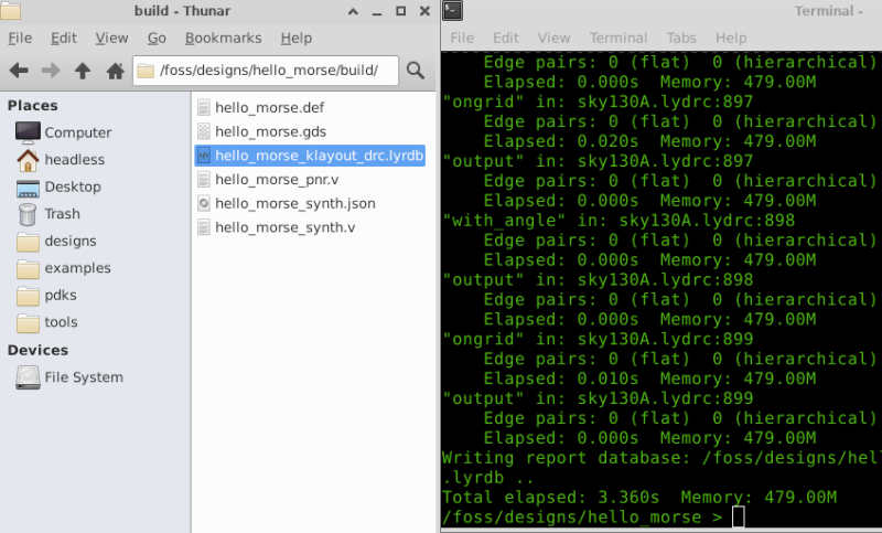
STEP1. full DRC → sky130A.lydrc
/foss/designs/hello_morse >  klayout -b build/hello_morse.gds \
  -r /foss/pdks/ciel/sky130/versions/54435919abffb937387ec956209f9cf5fd2dfbee/sky130A/libs.tech/klayout/drc/sky130A.lydrc
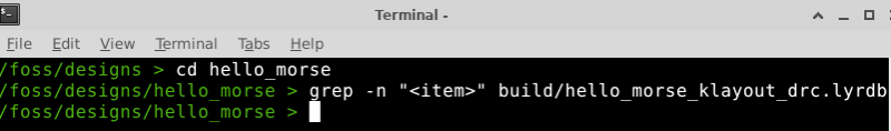
Output file: hello_morse_klayout_drc.lyrdb
STEP2. Open in KLayout to check DRC Marker
</>  Bash
klayout build/hello_morse.gds
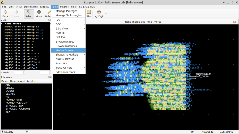
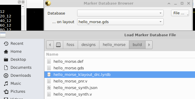
Choose File: build/hello_morse_klayout_drc.lyrdb
No Item
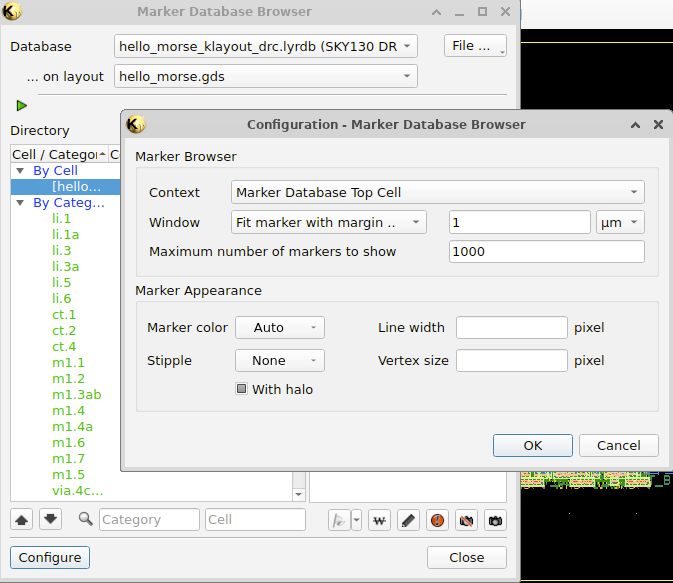
No DRC violations were found.
2. Document your chip: functionality, pin assignments, and interface details (e.g., timing parameters, frequencies, baud rates)
2. 1. Project Overview
- Title: Coloring Morse Beacon Chip - Kyunghee Yoo – Microelectronics 2026
- This project implements a Morse Beacon ASIC that converts a stored ASCII message into Morse code and transmits it through both a WS2812 LED strip and a 600 Hz buzzer.
- The system combines visual (LED) and auditory (buzzer) signals to improve human perception of Morse code. A push button allows users to change LED color, adding an interactive feature
2. 2. Functionality
- Converts ASCII characters into Morse code
- Outputs Morse signals through:
- WS2812 LED (
led_data) - Buzzer PWM (
buzzer_pwm) - Supports button-controlled LED color modes
- Automatically loops the message
- Stored Message (“Here I am”)
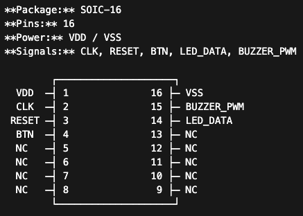
2. 3. Pin Assignments
| Pin | Name | Direction | Description |
|---|---|---|---|
| 1 | VDD | Power | Power supply |
| 16 | VSS | Power | Ground |
| 2 | CLK | Input | System clock |
| 3 | RESET | Input | Active-low reset (rst_n) |
| 4 | BTN | Input | Button input (btn_color) |
| 14 | LED_DATA | Output | WS2812 LED data signal |
| 15 | BUZZER_PWM | Output | 600 Hz buzzer output |
| 5–13 | NC | - | Not connected |
2. 4. Timing Parameters
The system operates with a clock frequency of 50 MHz.
The Morse unit time is defined as 100 ms, which serves as the base timing reference for all Morse code elements.
Morse Timing
| Element | Duration |
|---|---|
| Dot | 1 unit (100 ms) |
| Dash | 3 units (300 ms) |
| Symbol gap | 1 unit (100 ms) |
| Character gap | 3 units (300 ms) |
| Word gap | 7 units (700 ms) |
2. 5. Frequencies
The buzzer output operates at a frequency of approximately 600 Hz, generating an audible tone during active Morse symbols.
WS2812 Signal Timing
The WS2812 LED driver follows strict timing requirements for data transmission:
| Signal | Time |
|---|---|
| T0H | ~0.4 µs |
| T0L | ~0.8 µs |
| T1H | ~0.8 µs |
| T1L | ~0.4 µs |
| Reset | ~50 µs |
2. 6. Internal Architecture
- ASCII-to-Morse lookup table
- Morse timing state machine
- LED color controller (button input)
- WS2812 LED driver
-
PWM-based buzzer generator
-
Baud rate: N/A (Morse time-based encoding)
- Morse unit rate: 10 symbols/sec
- WS2812 data rate: ~800 kbps
The system operates as a sequential state machine that controls symbol timing, gaps, and message repetition.
3. Develop a verification test plan
- Morse Beacon - Power up, see LEDs flash Morse code
| Test | Equipment | Procedure | Expected Result |
|---|---|---|---|
| Test 1 — Power-up | Power supply, Oscilloscope | 1. Apply clock and power 2. Release reset 3. Observe outputs |
- Morse transmission starts automatically - LED and buzzer outputs are active |
| Test 2 — Morse Timing | Oscilloscope / Logic Analyzer | 1. Probe led_data2. Measure ON/OFF durations |
- Dot = 1 unit (~100 ms) - Dash = 3 units - Symbol gap = 1 unit - Character gap = 3 units - Word gap = 7 units |
| Test 3 — Buzzer Synchronization | Oscilloscope | 1. Probe buzzer_pwm2. Measure frequency and timing |
- Buzzer active only when LEDs are ON - Frequency ≈ 600 Hz |
| Test 4 — Color Change | Visual inspection, Logic Analyzer (optional) | 1. Press btn_color2. Observe LED output |
- LED color cycles through modes - Morse timing unaffected |
| Test 5 — Message Loop | Visual inspection, Logic Analyzer | 1. Observe full transmission cycle 2. Monitor restart timing |
- Message repeats after completion - Restart occurs after word gap |
4. Prepare your presentation for Thursday!
Class Note
1. Why package a chip?
The silicon die is tiny and fragile, Packaging provides protection, concectivity, heat dissipation, handling.
2. Package Types
modern surface mount packages: SOIC, QFP, QFN(Quad Flat No-lead)
3. Wirebonding
Wirebonding conncects the die pads to the package leads using thin gold or aluminum wires. For your design, you need to specify: Which die pad connects to which package pin, Power (VDD) and Ground (GND) assignments, Any special requirements (short wires for high-speed signals). Tip: Keep power/ground pads on opposite sides of the die from signal pads to simplify routing and reduce noise coupling.
4. Evaluation Board Design
KiCad is a free, open-source PCB design tool. Workflow: Schematic(circuit connection) –> Footprint(physical package shape) –> Layout(Place components and route traces) –> Gerbers(manufacturing file) PCB fabs: JLCPCB, PCBWay, OSH Park
5. Power Integrity
Layout Tips: * Keep decoupling caps close - Place 100 nF within 5mm of VDD/GND pins * Short, fat traces for power - Minimize resistance and inductance * Ground plane - Use a solid copper pour for GND if possible * Separate analog and digital grounds - Join at one point near power input * Check current capacity - 10 mil (0.25mm) trace handles ~0.5A; our designs need much less
6. I/O Voltage Levels
| Scenario | Solution |
|---|---|
| 1.8V chip ↔ 3.3V Arduino | Level shifter IC or resistor divider for inputs |
| 1.8V chip ↔ 5V Raspberry Pi | Level shifter IC (bidirectional) |
| 1.8V chip → 3.3V LED | Direct connection OK (LED just needs current) |
| 3.3V sensor → 1.8V chip | Resistor divider (slow) or shifter (fast) |
7. FPGA Prototyping
Filed Programmable Gate Array is like a breadboard for digital logic. Reprogrammable anytime, fast iteration raher than ASIC. If it works on the FPGA, it will probably work on silicon

# Synthesize for FPGA (iCE40 example)
yosys -p "synth_ice40 -top my_design -json my_design.json" my_design.v

# Place and route
nextpnr-ice40 --up5k --json my_design.json --pcf pins.pcf --asc my_design.asc

# Generate bitstream
icepack my_design.asc my_design.bin

# Program the FPGA
iceprog my_design.bin
8. Bring up and Testing
For Our Projects: * Fortune Teller - Press button, see output on serial terminal * Pocket Synth - Press keys, listen to speaker * Dice Roller - Press button, see 7-segment display * Morse Beacon - Power up, see LEDs flash Morse code
9. Debug Techniques
Debug Strategies * Divide and conquer: Isolate which block is failing, Test inputs and outputs of each block * Compare to simulation: Apply same inputs as testbench, Do outputs match? * Add observability: Route internal signals to spare pins, Add debug registers (if you planned ahead!)
Design for Debug (DFD) Plan ahead in your design: Spare I/O pins for probing internal signals, Bypass modes to isolate blocks, Status registers readable via serial