Session8. Final Presentation
(Thur Mar 12) The head of Fab Futures encouraged us to complete the project during the one-week extension. It has been challenging but necessary, and I am grateful to his decision.
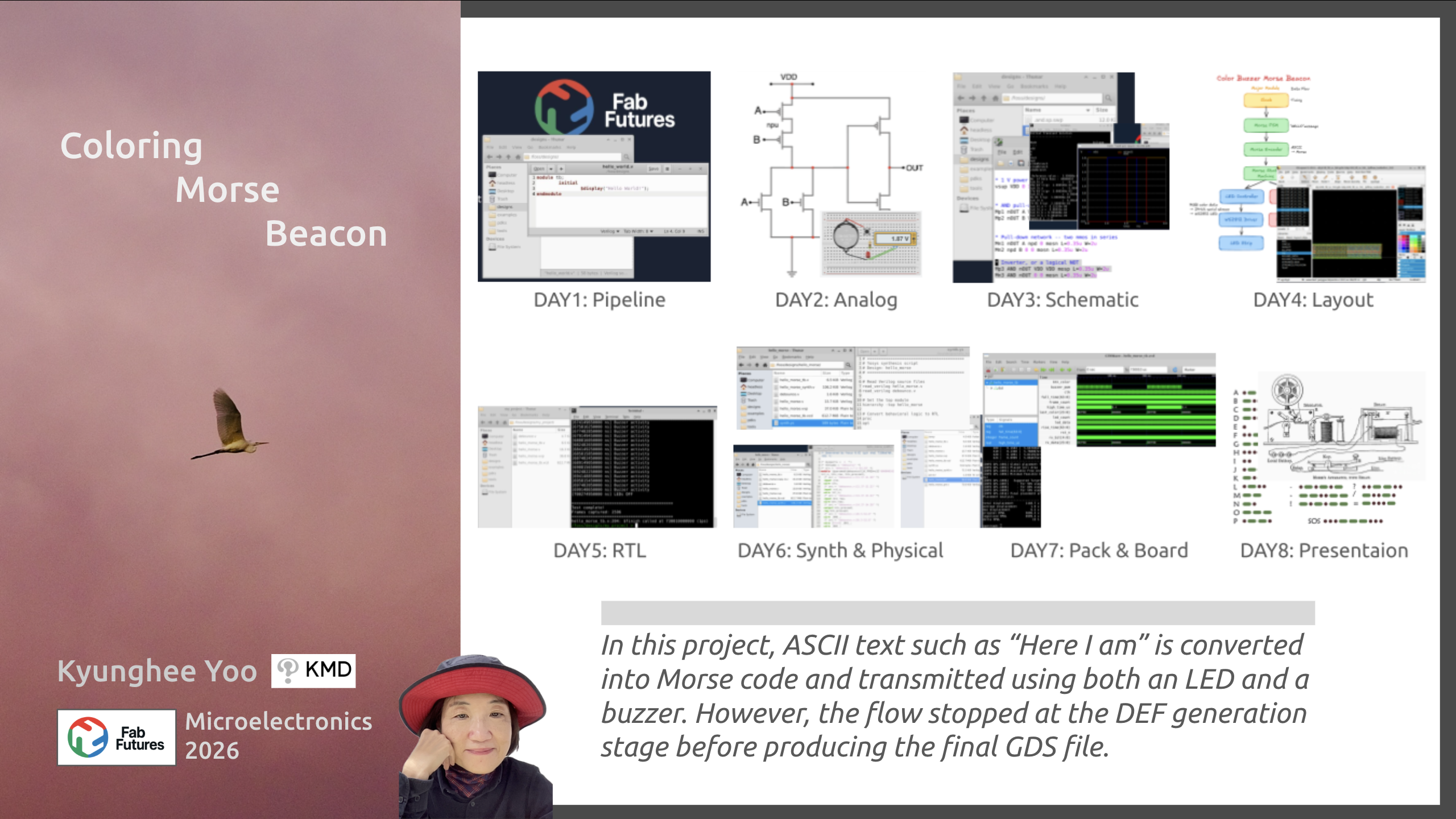
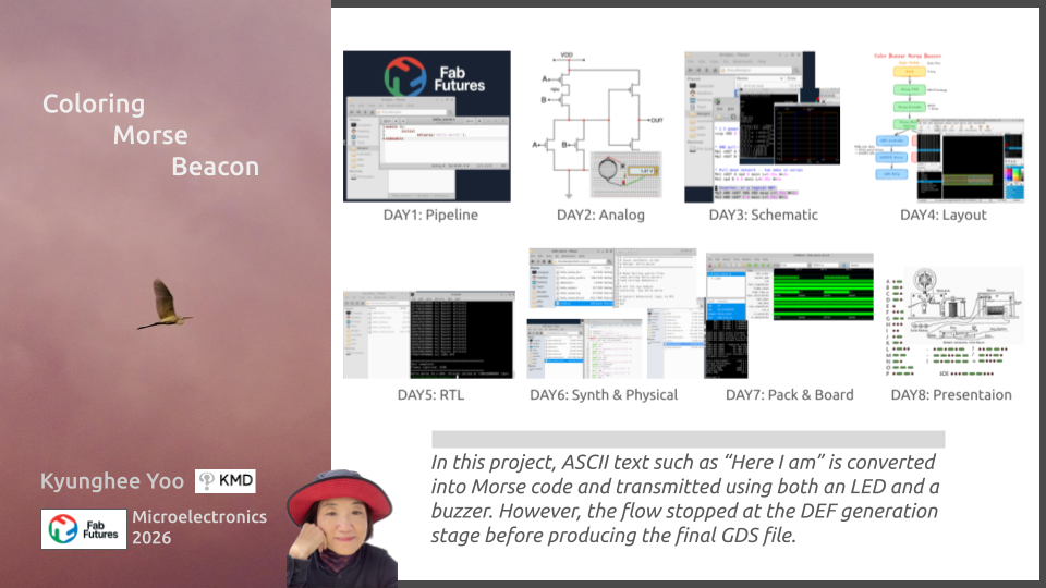
What you build:
- Customize an example or design your own
- Write/modify ~30-100 lines of Verilog
- Take it through the full flow: simulate → lint → synthesize → P&R → GDS
- Demo your chip at the end of week 4
I refered from the classmates’pages and used AI tools.
1. Morse Beacon Concept
The human desire to connect with others across distance and time has driven the technological evolution and continues to inspire communication systems today.
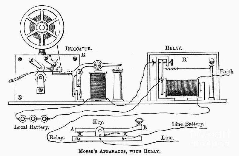
The morse electrical communication is an early form of electronics communication. It represents information using dot( . ) and dash( _ ) signals, similar to a simple 1-bit system that can be interpreted like binary 0 and 1. These signals are mapped to characters, forming the basis of digital communication. This idea eventually led to the rapid development of modern telecommunication.
The goal of this project is to create a device that helps people communicate using the rhythm of Morse signals, even if they do not know English.
I remember the low buzzer sound of a Morse telegraph. Even without knowing Morse code, the steady rhythm of short and long signals was easy to notice. Combining sound(beep) and visual(telegraph’s movement / LED) makes the signal even clearer to humane mind.
In my microelectronics module, ASCII text such as “Here I am” is converted into Morse code ” .... . .-. . / .. / .- – “ and transmitted using both LED and a buzzer. The LED color can be changed using a button, increasing an interactive experience within morse beacon.
Museum of the American Railroad

2. Chip Design and Demo
2-1. Presentation Day (Mar 12)
 My goal was to design a customized Morse Beacon chip, a project that allowed me to align my theoretical understanding with physical fabrication.
Starting with Verilog, I built a module for ASCII-to-Morse conversion, verified through simulation. The transition from synthesis (Yosys) to physical routing (OpenROAD) was a masterclass in discretion and detail. I spent considerable time refining the design to address timing issues and RC settings.
Final Presentation Page | Final Presentation Video
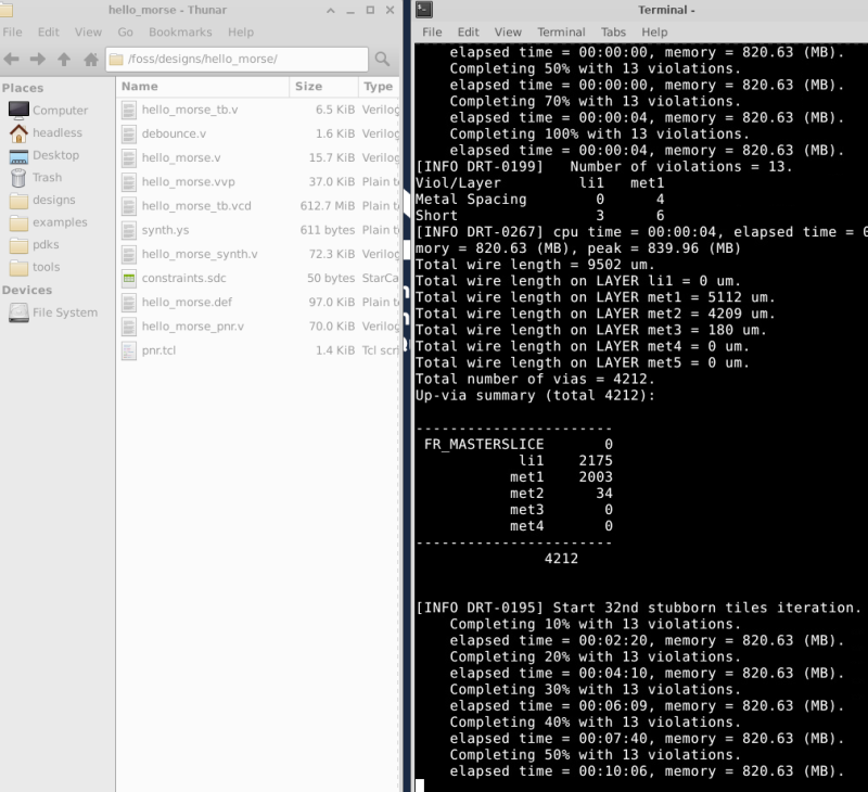 The terminal of my MacBook Air is still calculating hello_morse.def.
Today is the deadline, so I’ll stop running here.
Thank you to everyone who has ventured together for four weeks.
Happy Microelectronics 2026!
The terminal of my MacBook Air is still calculating hello_morse.def.
Today is the deadline, so I’ll stop running here.
Thank you to everyone who has ventured together for four weeks.
Happy Microelectronics 2026!
2-2. Supplementary Report (Mar 19)
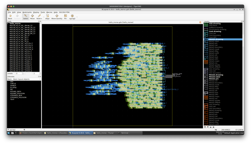
 I resolved routing-related errors—such as tie-cell insertion—which were critical to stabilizing the architecture. This iterative process culminated in a successful global routing and the production of the GDS file. Completing the DRC and technical documentation marked the final milestone in this fabrication journey.
-
Block Diagram
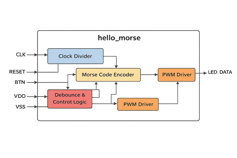
-
Circuit
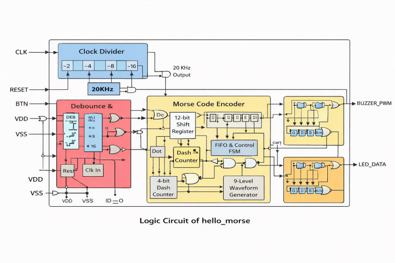
-
Schematics
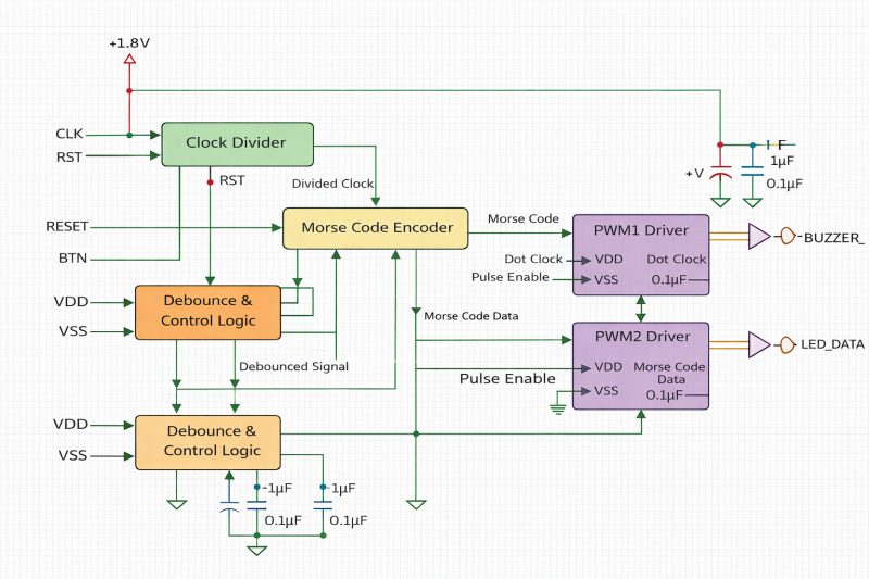
-
Verilog
</> iverilog -Wall -g2012 -Ilib -o hello_morse.vvp hello_morse.v
</> vvp hello_morse.vvp
code

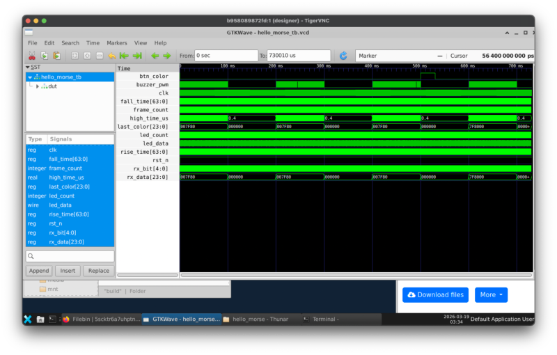
- Simulate
</> make sim-hello
</> gtkwave hello_morse_tb.vcd
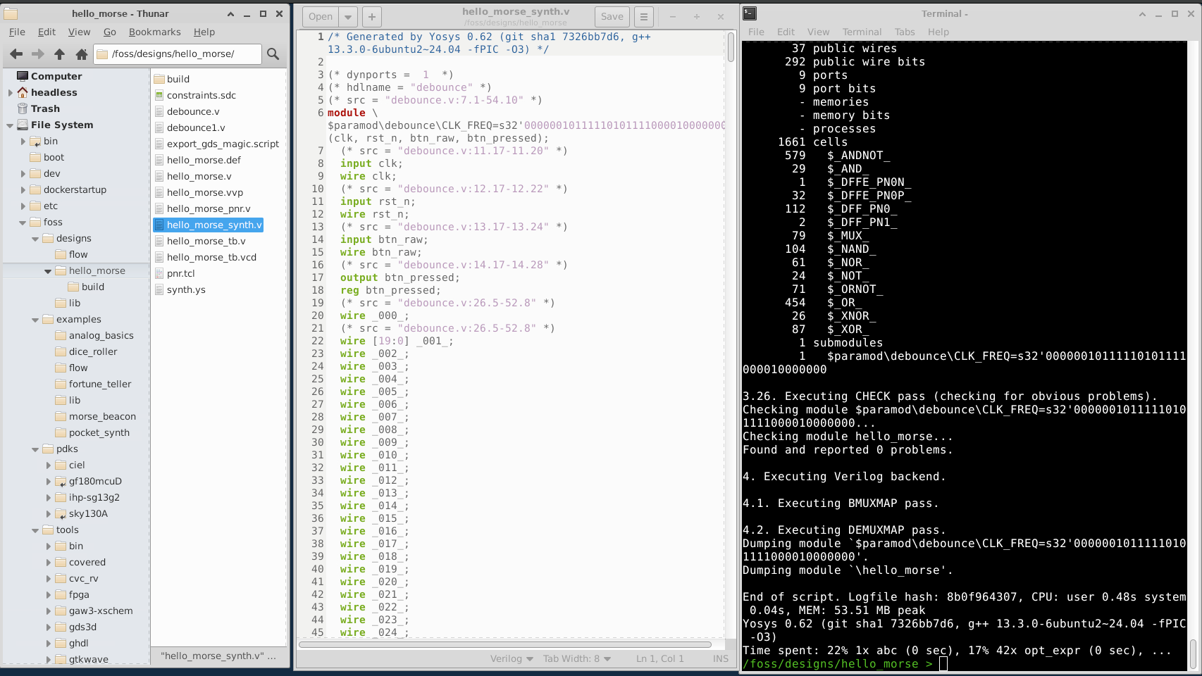
- Synthesize
</> yosys -p "read_verilog hello_morse.v debounce.v; synth -top hello_morse; write_verilog hello_morse_synth.v"
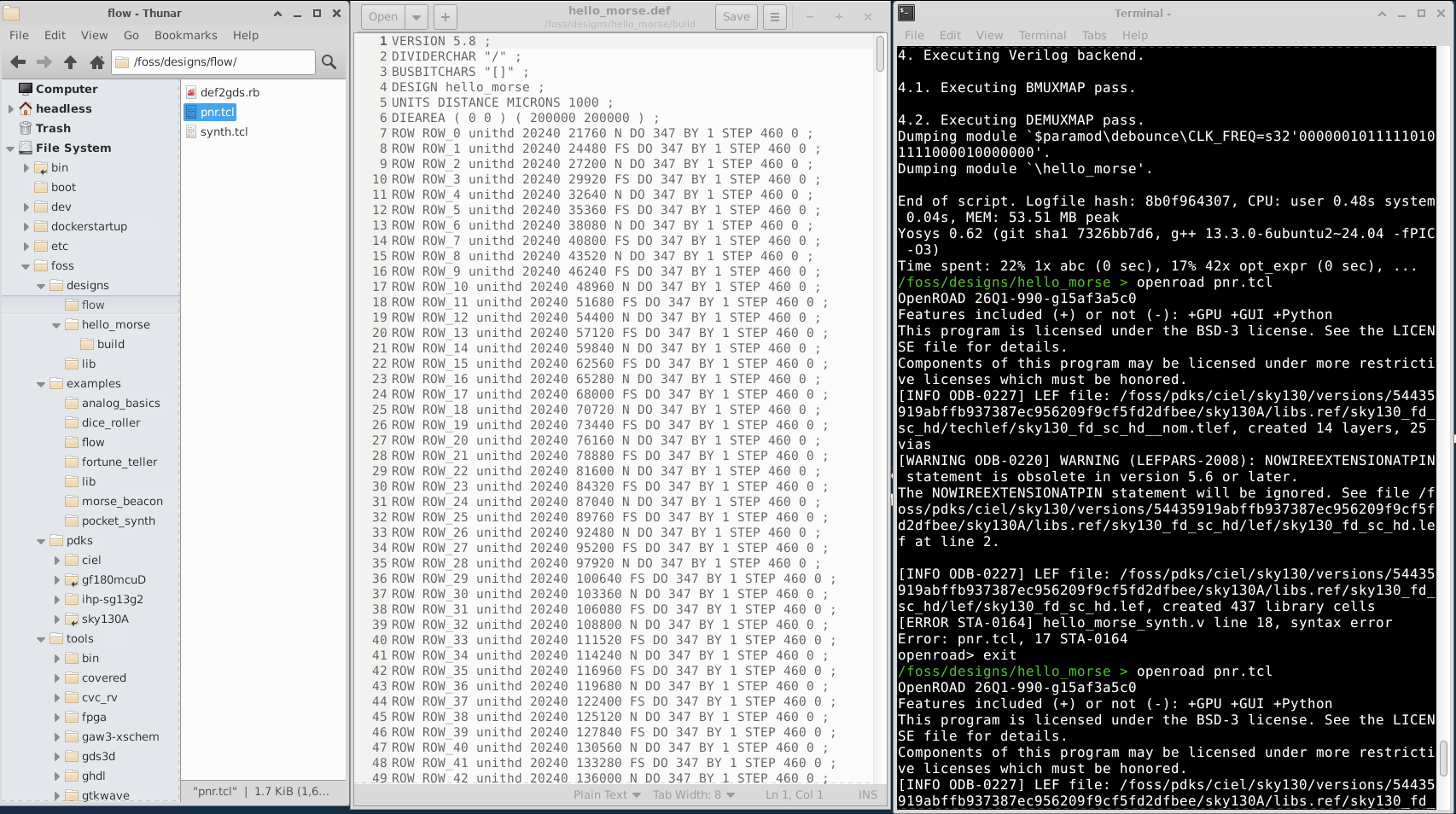
- Place&Routing
</> openroad pnr.tcl
-
GDS </>
make view-hello-gds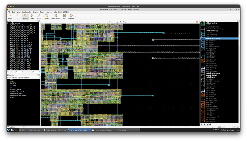
-
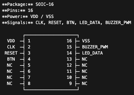
Pin Assignments
| Pin | Name | Direction | Description |
|---|---|---|---|
| 1 | VDD | Power | Power supply |
| 16 | VSS | Power | Ground |
| 2 | CLK | Input | System clock |
| 3 | RESET | Input | Active-low reset (rst_n) |
| 4 | BTN | Input | Button input (btn_color) |
| 14 | LED_DATA | Output | WS2812 LED data signal |
| 15 | BUZZER_PWM | Output | 600 Hz buzzer output |
| 5–13 | NC | - | Not connected |
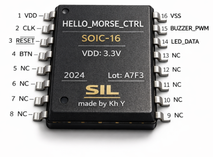
- Microcontroller Chip “SIL” (Concept Image)
- Assembled PCB board “Coloring Wing” (Concept Image)
![]()