Final Project > Research & Ideation
Where to start?!!
Nearly 3 weeks of classes and the Final Presentation in a week, I really need to decide on a project.
But at this point I am just beginning to grasp the subject of ASIC design (learning new tools, new jargon, new coding languages, new concepts), barely processing the new knowledge and not in a position to think about how to synthesize it all into a presentable project.
My path to the end doesn’t feel at all linear, more like a random walk in the forest…tracing chaotic lines that will hopefully resolve itself into a rational image at the end.
Stuck on Synthesizers
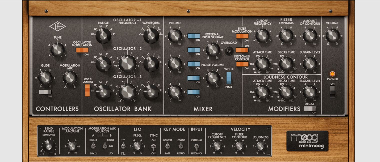
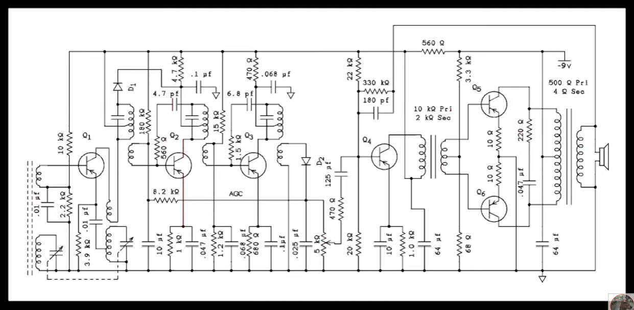
*Image from AudioZ *
So I really have it stuck in my head that I want to make a synthesizer component as my final project. The Analog Synthesizer that I have been building in my lab can be subdivided in to a few major circuit modules: the oscillators, the filters, the envelope generator, the low frequency oscillator (LFO), and the amplifier.
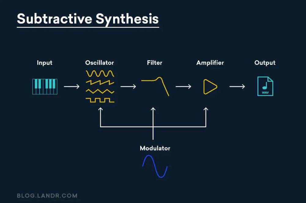
It all starts with the oscillator, the generator of sound. And different oscillators are basically different waveforms, singularly or in combination. So I revisited the circuits of 2 of the most fundamental waveforms.
-
Square Wave Generator > making a Relaxation Oscillator.
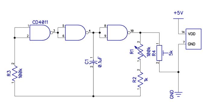
-
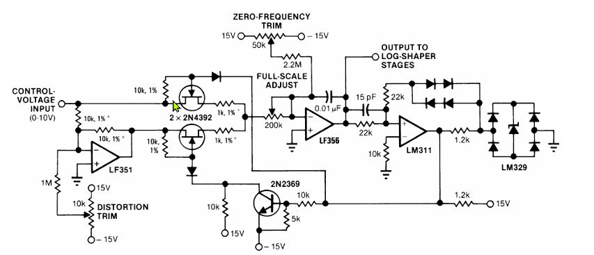
Sine Wave Generator > making a Voltage Controlled Sine Wave Oscillator.
I know how to build an Analog synthesizer using discrete electronics components, but how to implement it on a chip?
I need help!
Time to talk to ‘Chatty’.
Ideating with AI
A Digitally Controlled Ring Oscillator
This idea came from ChatGPT with the following prompts:
Me: “I want to create a simple chip design for Tiny Tapeout that would be useful for an analog synthesizer. what recommendations do you have”
ChatGPT: “If you tell me which Tiny Tapeout run/PDK you’re targeting (sky130 vs others) and how many analog pins you want to pay for (often 1–2 is enough), I’ll suggest a concrete block diagram + pinout (ua[0..], ui_in/uo_out) that matches the TT templates and constraints.”
me: “sky130 and this will my first attempt at chip design using verilog rtl. i like the idea of the relaxation oscillator, is it too complicated for a hello world project?”
ChatGPT produced this answer:
The good first project: a digitally controlled ring oscillator. This is very doable as a Tiny Tapeout “hello world” and is still musically useful:
-
A ring oscillator (odd number of inverters/NANDs in a loop) → gives a square wave.
-
Add a divider / prescaler → bring it into LFO/audio range.
-
Add stage-select / mux → coarse frequency control (select different tap lengths).
-
Optional: PWM or PDM output → easy “DAC-ish” CV/audio with an external RC filter.
That gets you something you can plug into a synth as:
-
clock source
-
crude VCO/LFO
-
digital noise-ish source (with jitter)
-
PWM tone generator
Me: “I really need to create a Hello World project that can be run on TinyTapeout. Are there some great examples of smaller, easy-to-do TinyTapeout projects that have been done in the past?”
ChatGPT: “Sure, there are plenty of simple, “hello world” style designs people have done on Tiny Tapeout. A classic one is a basic LED blinker. You just design a small circuit that toggles an output pin at a slow rate. Another popular one is a simple counter. It increments on every clock cycle, and you can decode some bits to control LEDs or simple outputs. There are also basic logic gates or simple finite state machines. The key is to keep it minimal—Tiny Tapeout thrives on small, understandable designs. So, pick a simple digital behavior that outputs a signal, and that’ll do!”
Me: “Analog designs are not simple?”
ChatGPT: “Fair point—if you’re sticking to purely digital designs, that’s where Tiny Tapeout shines for beginners. Analog is complex, so a first project should keep to digital logic. Stick with something like a simple counter, a shift register, or a pattern generator. These are not only manageable, but they also give you that satisfaction of seeing outputs like LEDs blink or change pattern in a predictable way. Keep it lean and fun!”
Got it. Stick to digital.
Help from YouTube
Ok…that’s a start. (After conversing with ChatGPT) At least I now know that my expectations are too lofty for my knowledge and skill level. Poking around YouTube, I found this video which helped me to understand what a ‘Hello World’ ASIC project might be.
He made it sound easy (it isn’t). I learned:
- you can do chip designs in Wokwi
- what Tiny Tapeout is all about
Watching this video Analog Chip Design is an Art. Can AI Help? I understand better why an Analog design as my ‘Hello World’ project is a bad idea.

A very good overview with some interesting insights. I learned:
- Digital Signal = electrical current gate either shut fully (0) or open fully (1)
- Analog Signal = continue signal flow where the current value now is not so different from the previous or next value
- While there are typically less components for an Analog chip design, component size, shape and location on the board matters
- Parasitic Resistance and Parasistic Capacitance issues are a thing, amplified when things get smaller and thinner…affecting the performance of a circuit design
- Parasitic Extraction becomes a design challenge
- And maybe the most challenging aspect of Analog Chip design (unlike digital chip designs) there are no tried-and-tested tools to automate the process
- A huge amount of knowledge, know-how and experience plays into successful Analog chip design
- The Aesthetics of a board is meaningful, as it functions as one indication of a design that will work properly (or not).
Maybe a super simple Analog design will be something I tackle…after I survive past the end of this course. For now Analog design is out of reach.
Tiny Tapeout Website Tour
But still, the definition of what would constitute a beginner Tiny Tapeout project remains murky.
So I decided to visit the Tiny Tapeout Website (yes, it took me until now to do this most obvious thing), to see what insights I might learn. Here are some of the highlights of my website tour:
-
Tiny Tapeout Demo Board
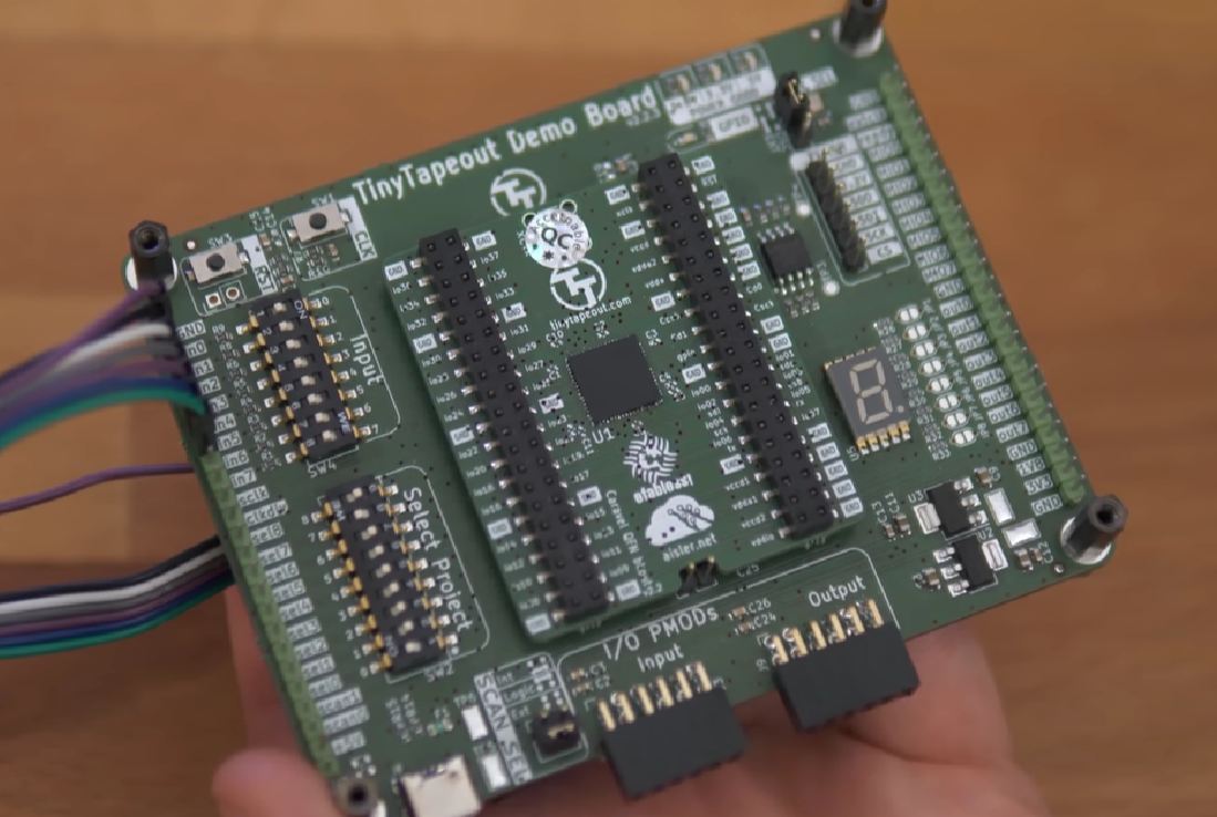
If I understand it correctly, a development board or ‘Demo Board’ is sent to Tiny Tapeout run participants after the production run. The chip wil contain yours and every other participant’s Tiny Tapeout project. The board will allow you to run all the hardware projects on the chip. -
Digital Design Learning. This page has a ton of learning resources about many of the terms and concepts that have been presented in the Microelectronics course. From the page, I learned…
- A Flip Flop is a circuit that can store 1-bit of information. It functions to synchronize signals and store information, allowing Sequential Logic to be performed. It functions as a gatekeeper to allow the current stored bit to remain as is or change, via an enable or activation signal
- A Full Adder performs mathematical addition function. Can handle a Carry value to prevent register overflow.
- A UART sends data serially (one after another) at a pre-specified data rate (Baud Rate). The 8N1 Protocol is the most common data frame protocol to send 8 bits with No parity bit and 1 stop bit.
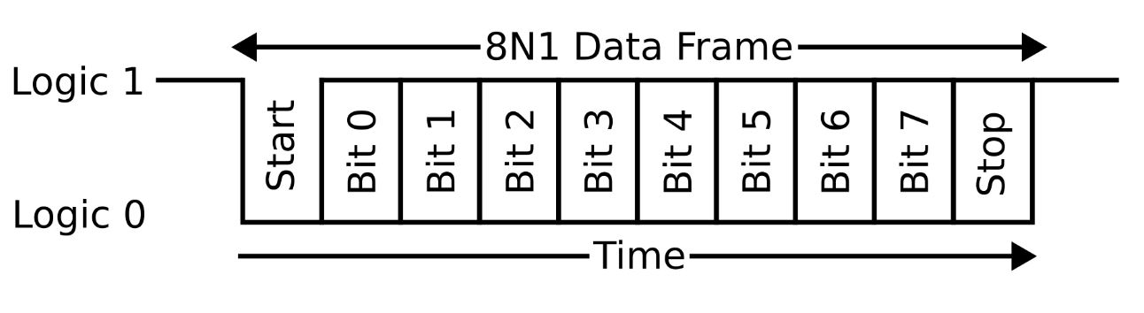 from Tiny Tapeout
-
Tiny Tapeout 8 Projects. All project pages for all previous Tiny Tapeout runs can be looked at here. It was very helpful and more than a bit intimidating to see what others have done. I would not want to put a stupid project on the chip that does very little and waste silicon space and production time.
-
Tiny Tapeout Designs on Wokwi Mind blown. People make their Tiny Tapeout schematic designs and simulation testing on Wokwi!
-
Tiny Tapeout - Working with HDLs. This page has a bunch of resources for Hardware Description Language work.
Preparatory Review
In the Microelectronics course, we have learned so much in such a short time that I have lost track of how everything relates to another. I thought I would spend some time to map out and understand the ASIC workflow again.
From design to ASIC fabrication:
Conceptualize the Functionality of a Small Chip Design
- Answer > What do I want the chip to do?
- ex: “Blink and LED when a button is pushed”
- Make a functionality flow diagram
Write Verilog RTL Code
- Describe the conceptual functionality as data-level (RTL) code descriptions
- Use Icarus-Verilog
Simulate the design
- Test the RTL code in simulation to ensure the functionality works as expected
- Use Icarus-Verilog
View simulation waveforms
- Review waveforms generated by the simulation to confirm correct functionality
- Use GTKwave
Synthesize RTL into Gate Level representation
- Convert RTL code into a gate-level description of the hardware circuit
- Use Yosys
Place & Route connection
- Define physical connections between gates and output GDS file
- Use OpenRoad
Inspect Layout
- Review chip design physical layout for errors
- Use KLayout
Send GDS to Chip Foundry for Fabrication
- Wait 6 months
- Pay > USD200
Tiny Tapeout Workflow Files
1. design.v
2. tb.v
3. sim.vcd
4. makefile
5. iverilog
6. gtkwave
7. klayout
Tiny Tapeout Toolchain:
- icarus verilog > simulation
- gtkwave > waveforms
- yosys > systhesis
- openROAD > PlAce & Route
- sky130 > Fabrication