Final Project > Production
As I learn more and understand more, my idea for the Final Project is also evolving. Here’s the timeline:
- Learning about the Moore Machine and State Case logic
- Turning ON and OFF an LED with a Button using State Case logic
- Playing a tone with a Button using State Case logic
- Playing a musical chord with a Button using State Case logic
…now I want to see if I can replicate my HiChord synthesizer functionality as a project.
7 Buttons that trigger diatonic Chords using State Case logic
Hi-Chord Synthesizer
The HiChord synthesizer has 7 keys that each play diatonic scale chords, instead of individual notes. The Diatonic scale in C:
- C major > C E G
- D min > D F A
- E min > E G B
- F major > F A C
- G major > G B D
- A min > A C E
- B dim > B D F
Final Project > 7-button Diatonic Chord Monophonic Synthesizer Chip
During the Final Project Development phase, a 1-button Chord Generator with Prescaler code was vibe-coded with ChatGPT’s help.
// Button-Chord State Machine - Clock Prescaler
module button_chord_FSM (
    input  clk,
    input  reset,
    input  ON,
    input  OFF,
    output reg audio_out
);

    //==================================================
    // State machine
    //==================================================
    reg state;

    localparam OFF_STATE = 1'b0;
    localparam ON_STATE  = 1'b1;

    always @(posedge clk or posedge reset) begin
        if (reset)
            state <= OFF_STATE;
        else begin
            case (state)
                OFF_STATE: begin
                    if (ON)
                        state <= ON_STATE;
                    else
                        state <= OFF_STATE;
                end

                ON_STATE: begin
                    if (OFF)
                        state <= OFF_STATE;
                    else
                        state <= ON_STATE;
                end
            endcase
        end
    end

    //==================================================
    // Prescaler: 50 MHz -> 1 MHz tick
    // 50 clock cycles of 50 MHz = 1 us
    // so make a pulse every 50 cycles
    //==================================================
    reg [5:0] prescaler;
    reg audio_tick;

    always @(posedge clk or posedge reset) begin
        if (reset) begin
            prescaler  <= 6'd0;
            audio_tick <= 1'b0;
        end else begin
            if (prescaler == 6'd49) begin
                prescaler  <= 6'd0;
                audio_tick <= 1'b1;   // one-clock pulse
            end else begin
                prescaler  <= prescaler + 6'd1;
                audio_tick <= 1'b0;
            end
        end
    end

    //==================================================
    // Chord generator
    // Using 1 MHz tick so 16-bit counters are enough
    //
    // divider = 1,000,000 / (2 * f_note)
    //
    // C3 = 130.81 Hz -> ~3822
    // E3 = 164.81 Hz -> ~3034
    // G3 = 196.00 Hz -> ~2551
    //==================================================
    reg [15:0] counter1, counter2, counter3;
    reg tone1, tone2, tone3;

    localparam [15:0] C3_DIV = 16'd3822;
    localparam [15:0] E3_DIV = 16'd3034;
    localparam [15:0] G3_DIV = 16'd2551;

    always @(posedge clk or posedge reset) begin
        if (reset) begin
            counter1  <= 16'd0;
            counter2  <= 16'd0;
            counter3  <= 16'd0;
            tone1     <= 1'b0;
            tone2     <= 1'b0;
            tone3     <= 1'b0;
            audio_out <= 1'b0;
        end else begin
            if (state == ON_STATE) begin

                if (audio_tick) begin
                    // Tone 1: C3
                    if (counter1 == C3_DIV) begin
                        counter1 <= 16'd0;
                        tone1    <= ~tone1;
                    end else begin
                        counter1 <= counter1 + 16'd1;
                    end

                    // Tone 2: E3
                    if (counter2 == E3_DIV) begin
                        counter2 <= 16'd0;
                        tone2    <= ~tone2;
                    end else begin
                        counter2 <= counter2 + 16'd1;
                    end

                    // Tone 3: G3
                    if (counter3 == G3_DIV) begin
                        counter3 <= 16'd0;
                        tone3    <= ~tone3;
                    end else begin
                        counter3 <= counter3 + 16'd1;
                    end

                    // combine square waves
                    audio_out <= tone1 ^ tone2 ^ tone3;
                end
            end else begin
                counter1  <= 16'd0;
                counter2  <= 16'd0;
                counter3  <= 16'd0;
                tone1     <= 1'b0;
                tone2     <= 1'b0;
                tone3     <= 1'b0;
                audio_out <= 1'b0;
            end
        end
    end

endmodule
From 1 to 7 Buttons and Chords
My thinking is, if I can generate one chord with one button, it should not be heroic to make 7 chords with 7 buttons. What I think I will need to do:
- Add 4 more counters, 4 more tone registers and 4 more tone cases, for the other 4 tones in the scale
- Add explicit inputs for each button
- Add conditional statements to determine which button is being pressed and which tone state cases to activate.
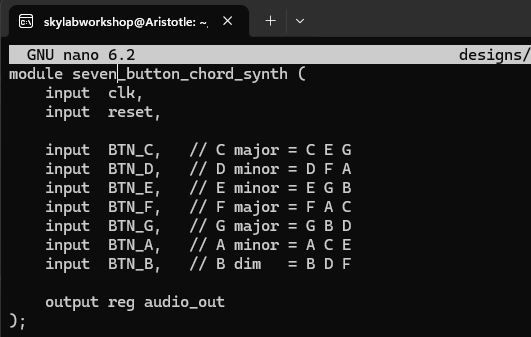
// 7-Button Diatonic Chord Monophonic Synthesizer Chip
// coded with ChatGPT assistance

module button_chord_7_optimized (
    input  clk,
    input  reset,

    //unique input for each of 7 chord button
    input  BTN_C,   // C major = C E G
    input  BTN_D,   // D minor = D F A
    input  BTN_E,   // E minor = E G B
    input  BTN_F,   // F major = F A C
    input  BTN_G,   // G major = G B D
    input  BTN_A,   // A minor = A C E
    input  BTN_B,   // B dim   = B D F

    output reg audio_out //assigned to always block
);

    // Clock Prescaler: 50 MHz -> 1 MHz
    reg [5:0] prescaler; //6-bit register
    reg audio_tick;

    // Prescaler Logic block
    always @(posedge clk or posedge reset) begin
        if (reset) begin
            prescaler  <= 6'd0;
            audio_tick <= 1'b0;
        end else begin
            if (prescaler == 6'd49) begin //count to 50
                prescaler  <= 6'd0;
                audio_tick <= 1'b1; //generate one audio tick
            end else begin
                prescaler  <= prescaler + 6'd1;
                audio_tick <= 1'b0;
            end
        end
    end

    // Prescaled Clock
    // divider = 1,000,000 / (2 * f_note)
    // generate 7 note frequencies
    localparam [15:0] C3_DIV = 16'd3822; // 130.81 Hz
    localparam [15:0] D3_DIV = 16'd3405; // 146.83 Hz
    localparam [15:0] E3_DIV = 16'd3034; // 164.81 Hz
    localparam [15:0] F3_DIV = 16'd2863; // 174.61 Hz
    localparam [15:0] G3_DIV = 16'd2551; // 196.00 Hz
    localparam [15:0] A3_DIV = 16'd2273; // 220.00 Hz
    localparam [15:0] B3_DIV = 16'd2025; // 246.94 Hz


    // Button handling
    // valid_chord = exactly one button is pressed
    wire [6:0] buttons; //7-bit signal line
    assign buttons = {BTN_C, BTN_D, BTN_E, BTN_F, BTN_G, BTN_A, BTN_B}; //assigns button names to each bit of the signal line (like an array) each to express a boolean value for pressed or unpressed

    // define signal lines
    wire any_pressed;
    wire more_than_one;
    wire valid_chord;

    // button press checks
    assign any_pressed    = |buttons; //verilog 'reduction OR', "is any button pressed?"
    assign more_than_one  = |(buttons & (buttons - 7'd1)); //"is more than one button pressed"
    assign valid_chord    = any_pressed & ~more_than_one; //"is only one button pressed?"

    // Selected divider values for currently active chord
    reg [15:0] div1, div2, div3;

    // Chord Selection Logic Block
    // Chord case states for each button
    always @(*) begin
        // default = silence
        div1 = 16'd0;
        div2 = 16'd0;
        div3 = 16'd0;

        if (valid_chord) begin
            if (BTN_C) begin
                // C major = C E G
                div1 = C3_DIV;
                div2 = E3_DIV;
                div3 = G3_DIV;
            end
            else if (BTN_D) begin
                // D minor = D F A
                div1 = D3_DIV;
                div2 = F3_DIV;
                div3 = A3_DIV;
            end
            else if (BTN_E) begin
                // E minor = E G B
                div1 = E3_DIV;
                div2 = G3_DIV;
                div3 = B3_DIV;
            end
            else if (BTN_F) begin
                // F major = F A C
                div1 = F3_DIV;
                div2 = A3_DIV;
                div3 = C3_DIV;
            end
            else if (BTN_G) begin
                // G major = G B D
                div1 = G3_DIV;
                div2 = B3_DIV;
                div3 = D3_DIV;
            end
            else if (BTN_A) begin
                // A minor = A C E
                div1 = A3_DIV;
                div2 = C3_DIV;
                div3 = E3_DIV;
            end
            else begin
                // BTN_B
                // B diminished = B D F
                div1 = B3_DIV;
                div2 = D3_DIV;
                div3 = F3_DIV;
            end
        end
    end

    // Three independent tone generators
    reg [15:0] counter1, counter2, counter3;
    reg tone1, tone2, tone3;

    // Tone Generator Logic Block
    always @(posedge clk or posedge reset) begin
        if (reset) begin
            counter1  <= 16'd0;
            counter2  <= 16'd0;
            counter3  <= 16'd0;
            tone1     <= 1'b0;
            tone2     <= 1'b0;
            tone3     <= 1'b0;
            audio_out <= 1'b0;
        end else begin
            if (valid_chord) begin
                if (audio_tick) begin
                    // tone 1
                    if (counter1 >= div1) begin
                        counter1 <= 16'd0;
                        tone1    <= ~tone1;
                    end else begin
                        counter1 <= counter1 + 16'd1;
                    end

                    // tone 2
                    if (counter2 >= div2) begin
                        counter2 <= 16'd0;
                        tone2    <= ~tone2;
                    end else begin
                        counter2 <= counter2 + 16'd1;
                    end

                    // tone 3
                    if (counter3 >= div3) begin
                        counter3 <= 16'd0;
                        tone3    <= ~tone3;
                    end else begin
                        counter3 <= counter3 + 16'd1;
                    end

                    // Chord Output
                    audio_out <= tone1 ^ tone2 ^ tone3;
                end
            end else begin
                // silence if zero or multiple buttons are pressed
                counter1  <= 16'd0;
                counter2  <= 16'd0;
                counter3  <= 16'd0;
                tone1     <= 1'b0;
                tone2     <= 1'b0;
                tone3     <= 1'b0;
                audio_out <= 1'b0;
            end
        end
    end

endmodule
Learnings from code above
- Learned ‘wire’ signal line definition
- Learned Verilog ‘reduction OR’ syntax
- Learned ‘assign’ command
Running Project Code through the RTL to GDS Toolchain
-
Launch Ubuntu 22.04 WSL
-
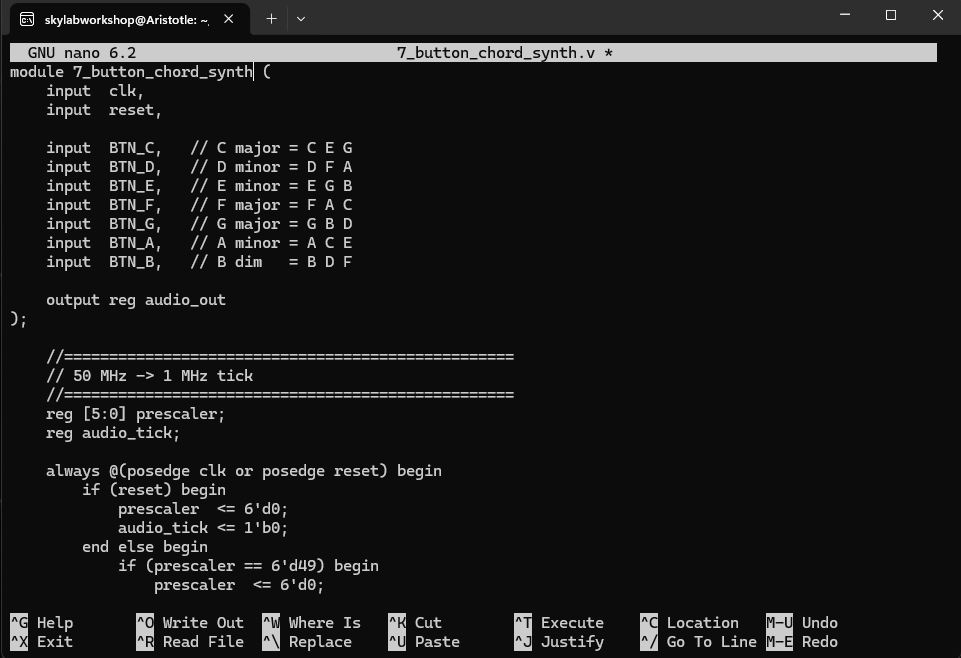
Run Nano to write Verilog RTL code for the 7-Button Chord Synth project
- Important: Locate the file in a specific location within the ‘src’ folder of the OpenRoad working directory
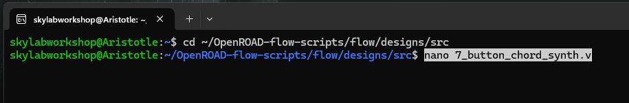
- Save > CTRL + o, ENTER
- Exit Nano > CTRL + x
- Important: Locate the file in a specific location within the ‘src’ folder of the OpenRoad working directory
-
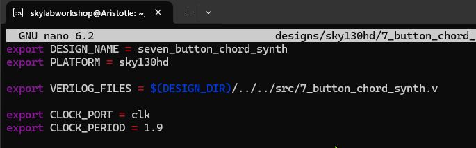
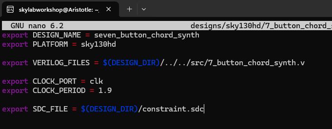
Write a sky130hd Configuration File in Nano
- Important: Locate the file in ‘designs/sky130hd/7_button_chord_synth’

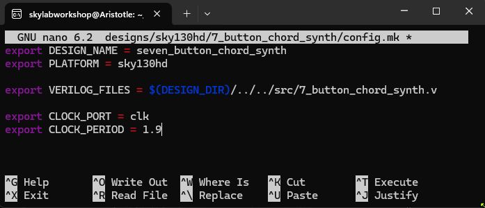
- Save > CTRL + o, ENTER
- Exit Nano > CTRL + x
- Important: Locate the file in ‘designs/sky130hd/7_button_chord_synth’
-
Synthesize Verilog RTL code into Logic Gates using Yosys
Converting RTL code to Gate-level Netlist

ERROR!
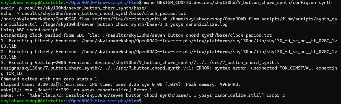
- ChatGPT informed me that my module name generated a syntax error
- The problem > my module name cannot start with a number
- ‘7_button_chord_synth’ must be changed to ‘seven_button_chord_synth’The Fix
-
Edit the Verilog RTL file
-
Edit the Config file as well (to reference the new module name)
Rerun Synthesis > Error - Again
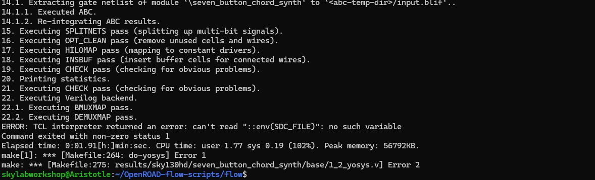
- ChatGPT advised that this error has to do with the config file not defining a Timing Constant File
- Timing Constant File (SDC) specifies: the clock, clock frequency, input/output timingThe Fix
- Create an SDC file (ChatGPT provided instructions)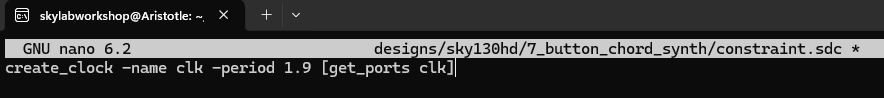
- Edit the Configuration File > adding a new line to point to the SDC file
Rerun Synthesis > Success!!
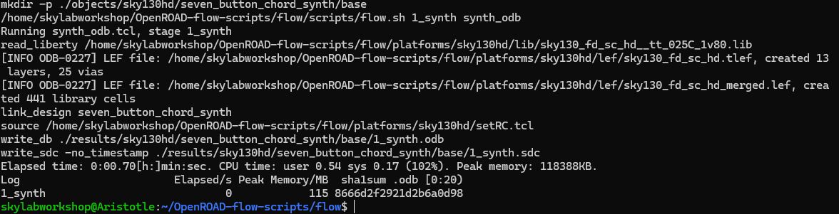
read_liberty … sky130_fd_sc_hd_tt_025C_1v80.lib
- loads sky130 Standard Cellsread_lef sky130_fd_sc_hd.tlef
read_lef sky130_fd_sc_hd_merged.lef
- loads the technology LEF…describes metal layers, vias, cell dimensionslink_design seven_button_chord_synth
- confirms successful link to the Verilog design file - module name matched, syntax is correct, all signals resolvedwrite_db ./results/…/1_synth.odb
- an OpenRoad database of the circuit was createdwrite_sdc ./results/…/1_synth.sdc
- clock constraints successfully appliedElapsed time: 0:00.70
- 0.7 seconds = fast compile hints at a small, Tiny Tapeout compatible circuit design -
-
Floorplanning
- Floorplanning will…determine the chip area, place IO pins, create a power grid (ChatGPT)
Run Floorplanning > ERROR!!
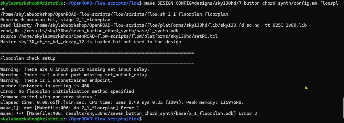
- ChatGPT tells me that the error has to do with the die area or core utilization specifications were not made
- Must edit the Configuration File again > adding 2 lines for DIE_AREA (chip boundary) and CORE_AREA (boudary for Standard Cell placement)
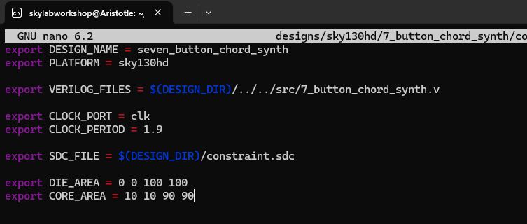
Run Floorplanning > Success!!
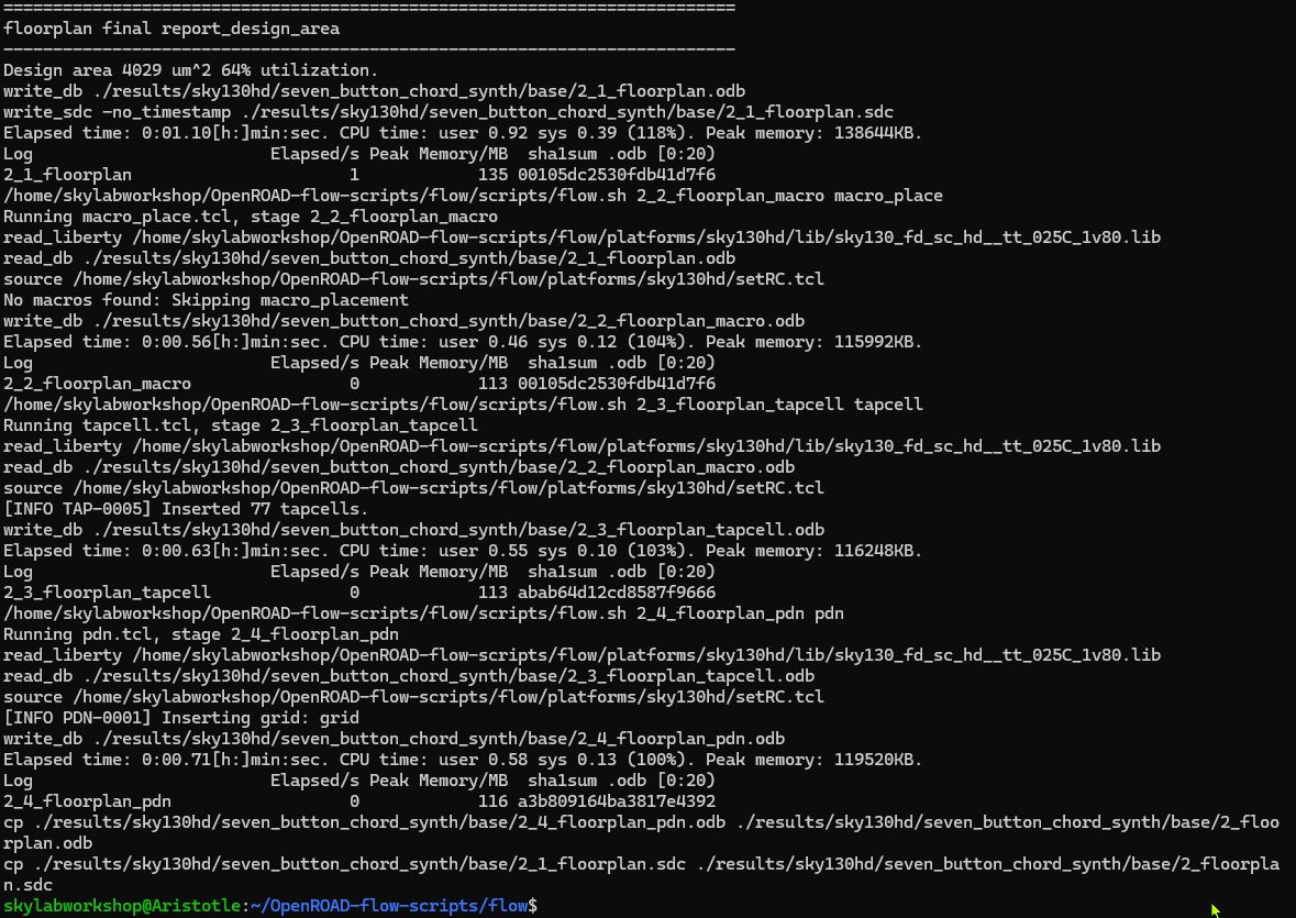
ChatGPT provided the following insights about the Floorplanning results:
Design area 4029 um^2 64% utilization
- 4029 square microns of area required & 64% are used for logic cells (the remainder available for routing > good)
- This compares to the Tone Generator design from Session 6 which was only ~500 square microns in sizeInserted 77 tapcells
- 77 Tapcells are used to connect substrate and wells to power, and prevent latch-upInserting grid: grid
- A Power Grid metal layers to distribute power was created (VDD, VSS)2_floorplan.odb
- An .odb file was created (6_1_merged.gds) containing: chip boundary, power grid, tapcells, and empty placement rows
- ..no standard cells were placed yet
-
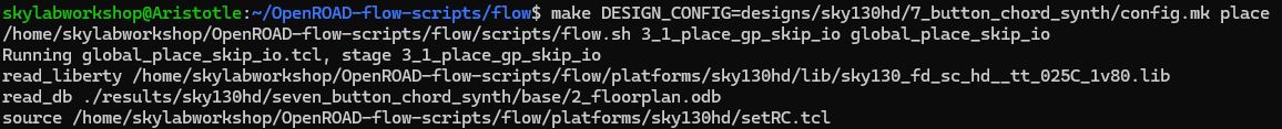
Logic Cell Placement
The last step, Floorplanning, defined the boundary and power foundation for the logic gates, similar to the foundation and mechanical systems of a building I suppose. In this step, the actual Logic Cells (from sky130hd library) that will make up the 7 Button Monophonic Chord Synthesizer will be build on top.
Run the Cell Placement > Success!!
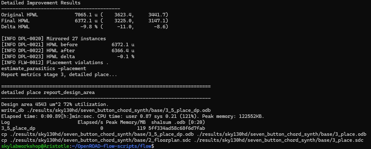
Wire Length Optimization (HPWL)
- Original HPWL > 7056.1 - Final HPWL > 6372.1 - Delta > -9.8% - Insight: wiring reduced by ~10% - Implications: shorter wires, lower capacitance, faster circuit, lower power > good!Cell Mirroring
- Mirrored 27 instances - Implications: better pin line-up, shorter wires > good!Placement Violations
- zero > placement is “physically legal”
- Implications: no overlapping cells, rows are valid, power rails line upUpdated Area
- Design Area > 4543 square microns (up from floorplanning 4029 square microns)
- Utilization > 72% (up from floorplanning 64% utilization) > still good! (50-70% is ideal)Files Generated
- Another .obd file (3_place.odb) generated containing: exact cell location, estimated parasitic wiring
-
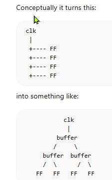
Clock Tree
Time to distribute the clock into the hardware layout, adding clock buffers, balance clock arrival times, prevent clock skew. The clock was previously represented as a single logical signal, which must reach all the Flip-flops on the chip. The CTS process builds a balanced clock distribution network using buffers…keeping clock arrival times nearly equal across the chip (ChatGPT)
Run Clock Tree > Success!!

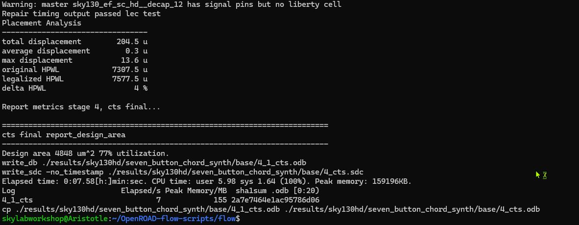
Repair timing output passed lec test
- buffers inserted
- timing optimized
- logic behavior verified > Verilog design still functions as expected
- LEC = Logic Equivalence Check completedImplications: - Original HPWL > 7307
- Legalized HPWL > 7577
- Delta > 4%
- …slight HPWL increase due to clock buffer and wire additionUpdated Chip Size:
- Design Area > 4848 square micron (up from 4543 square microns)
- Utilization > 77% (up from 72% square microns) > not idea, still safe (within 70-80% range, at 85% becomes problematic)Displacement Metrics
- Total Displacement > 204.5 microns
- Average > 0.3 microns
- Max > 13.6 microns
- …some cells were moved to make room for the Clock Tree
- …movement very small, placement still goodFile Generated
- Another .odb file (4_cts.odb) created that contains: placed Standard Cells, Clock Buffers inserted, Preliminary Clock Routing
- Signal Wires are still NOT routed yet
-
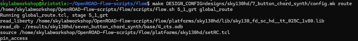
Routing
In this step, metal wires, vias, power connections and a clock network will be created. Reports will be generated.
Run Routing > Success!!
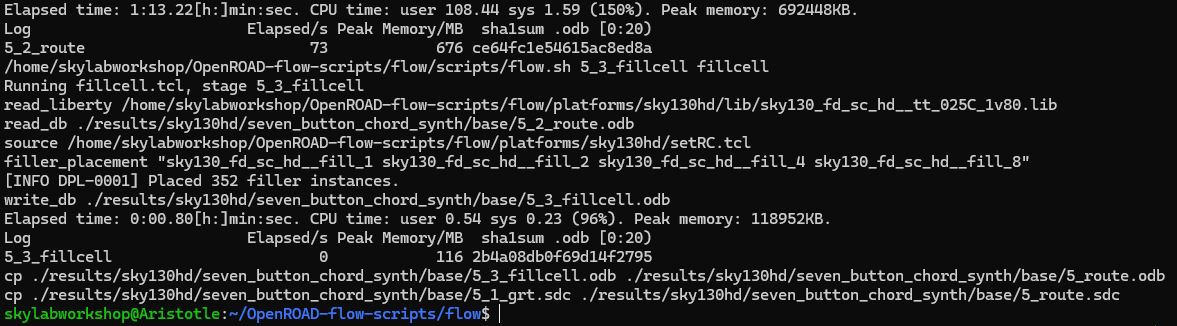
Elapsed time: 1:13.22
- (this process took a while…)
- According to ChatGPT, this step assigned metal layers, avoid wire crossings, placed vias, and obeyed design rules…computing “thousands of possible wire paths” to pick the “legal ones”
- Analogous to routing a PCB in KiCAD, I guess. Like trying to solve a puzzle.Placed 352 filler instances
- 352 Empty Standard Cells added between logic cells
- …to “maintain well continuity, power rails and satisfy fabrication rules”
- Well Continuity is a physical-silicon concept…the doped region between the Metal Layer (top) and the Silicate Substrate (bottom) where CMOS and NMOS transistors “live”
- Wells must be continuous…to avoid voltage float, leakage, latch-up, incorrect transistor thresholds and chip failure
- …Empty Cells are used to fill gaps and maintain continuityFiles Generated:
- Two new .odb files were generated (5_route.odb and 5_3_fillcell.odb)
- …the chip layout is now fully connected!! -
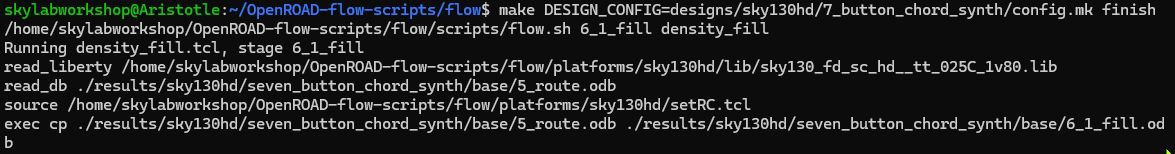
Final Analysis & GDS Export
According to ChatGPT, in this Final Stage many verification analysis and checks are performed including:
- Final Timing analysis
- IR Drop Analysis
- Antenna Checks
- Final Design Rule Checks (DRC)
…and ends with a GDS file (actual silicon mask layout) export.
Feels like the Boss Battle in a game.
Run Final State > Success!!
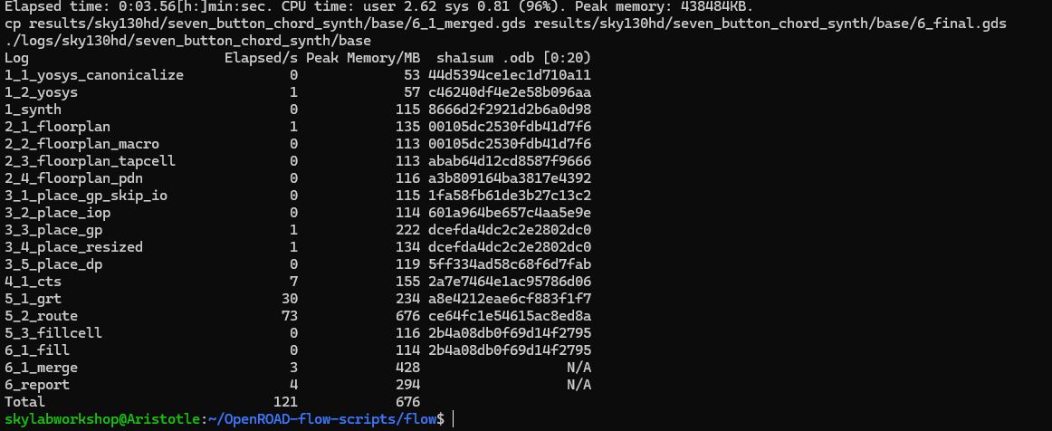
cp results/sky130hd/seven_button_chord_synth/base/6_1_merged.gds
- Confirms the export of the all important GDS file for Fabrication - Contains: Transistor geometries, wells, diffusion, metal wires, vias, power rails
The 7 Button Diatonic Chord Monophonic Synthesizer ASIC > Report
- ~450 logic cells
- ~350 filler cells
- ~4800 square microns in size
- 77% Utilization
Synthesis Report
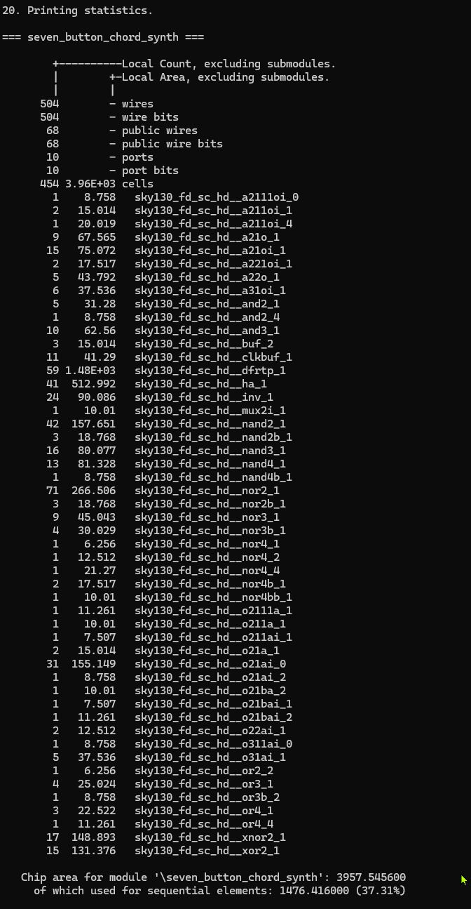
Summary: Standard Cell Counts
- NOR2 > 71
- D Flip-Flops > 59
- each with ~24 transistors
- so ~1400 transistors for Tone Counters, State Registers & Button Logic State
- NAND2 > 42
- Half Adders > 41
- for Note Frequency Dividers
- ~570 transistors
- Combinational Logic > ~250
- Inverters, XNOR, XOR gates
- for Button Selection, Chord Mapping, Comparator Logic, Tone Toggling
- ~2000-2500 transistors
- Total > 465 Standard Cells (including Combinational Logic), ~4000-~4500 transistors
Finished Report
ChatGPT reviewed my final report and identified a problem:
-
The design does not meet the clock target asked for
-
Required time to achieve fmax > 2.197
- Finish Critical Path Delay > 2.3574
- Finish Critical Path Slack > -0.2277
Recommendation:
- Reduce fmax to 400MHz
- Change the export CLOCK_Period configuration from 1.9 to 2.5
- “The desired audio frequencies are extremly low compared to hundreds of MHz, so the chip doesn’t need to run ultra fast”
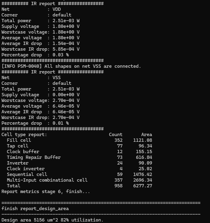
Report Conclusions:
- Routing & Layout > success
- Fabrication File > success
- Timing > slightly failing
- Clock target > too aggressive
- Adjust the export clock in the config.mk file and constraint.sdc to 2.5
- run make clean command
- rerun the process
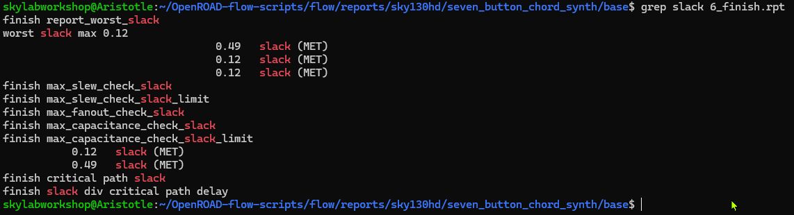
Results After Adjustment and Rerun
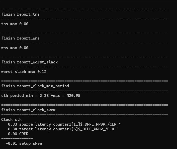
timing now met, timing closure achieved
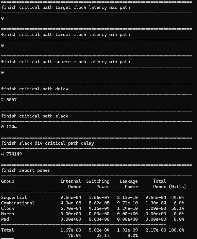
- Finish Critical Path Delay > 2.6057
- Finish Critical Path Slack > 0.1244
Power Consumption
- Sequential > 0.954 mW
- Clock > 1.09 mW
- Combinational > 0.13 mW
DRC & LVS
DRC ran without issue. Here is the DRC Report.
LVS was harder. With the toolchain I had, mostly a collection made available by installing OpenRoad, the .tech file needed for LVS check with Magic was missing. After debugging with ‘Chatty’ for a while, the conclusion was to go with KLayout for the LVS check.
Error in Magic
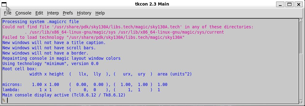
.tech File not Found

Support File Mismatch
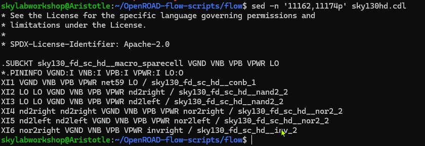
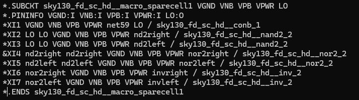
A “Failing Subcircuit
.SUBCKT sky130_fd_sc_hd__macro_sparecell1 VGND VNB VPB VPWR LO
This definition has 5 pins. But later inside CDL (circuit description language, i.e. SPICE), the same cell is being instantiated with 6 or 7 pins…causing LVS Parser to stop. ChatGPT describes this as a “quirk of the OpenRoad-flow-scripts Sky130 CDL” when used with KLayout LVS.
Some “Spare Cells Definitions” don’t parse cleanly, causing “pin count mismatch between circuit definition and circuit call”
Fortunately, the problematic cell is a “Filler Cell” and inconsequential for the functionality of the project circuit. So it can be safely removed for LVS testing.
One error managed…another one appears.
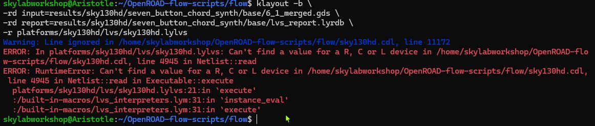
- A Passive Device Line is encountered that does not have a required value.
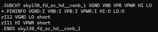
- Two resistors do not have values
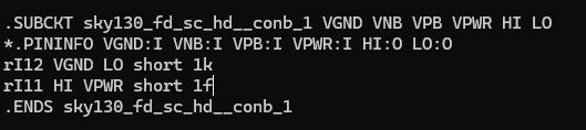
- Arbitrary values added to satisfy LVS requirements
- LVS does not concern itself with values, only connectivity
But another error appears…
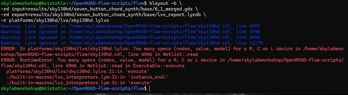
At this point, ChatGPT advises that the issue is not with the chip design, but with syntax incompatibility between OpenRoad CDL, KLayout LVS and Sky130 device. To stop chasing ghosts, ChatGPT states the solution will require the installation of the full Sky130 PDK stack (a multi-gigabyte install)…then run LVS with Magic and Netgen.
I am choosing not to do this. As ChatGPT states that my design is a pure standard-cell digital logic so LVS checks should not be a problem.
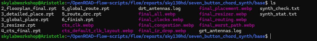
WEBP Images
Generated as part of the final report by OpenRoad. The WEBP files can be opened in Windows from WSL by…
- Navigating to the correct folder
cd ~/OpenROAD-flow-scripts/flow/reports/sky130hd/seven_button_chord_synth/base
- Run the Explorer command
explorer.exe .
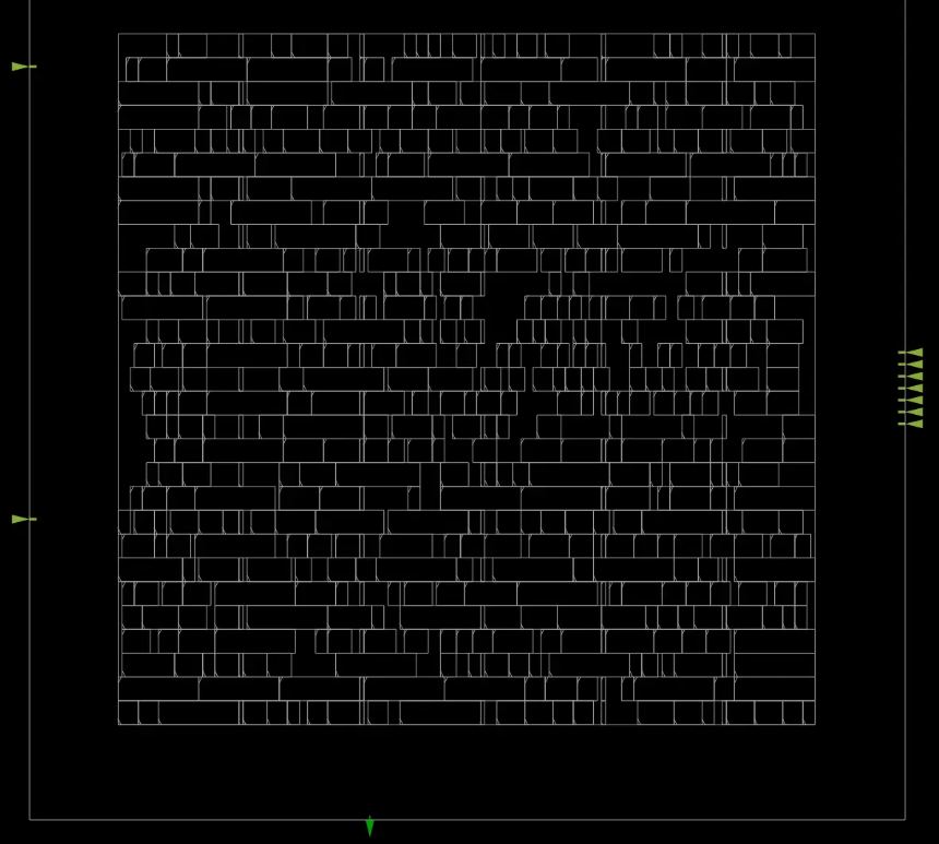
Final Placement
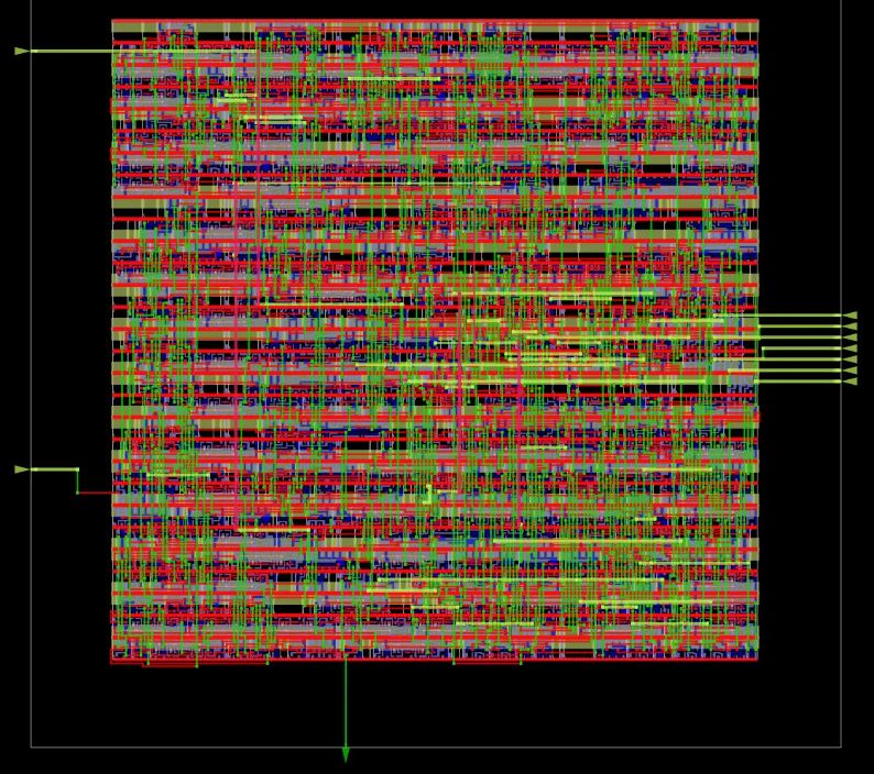
Final Routing
Final Clock
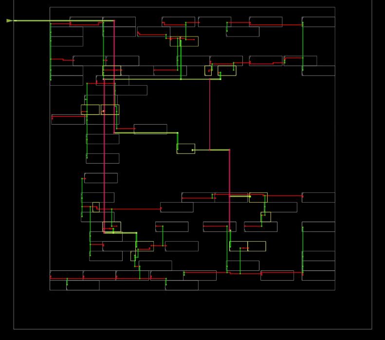
Final Worst Path
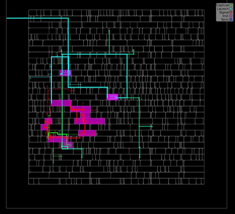
The image shows the Critical Timing Path traced across the chip layout…specifically the longest delay path in the entire chip
- Green rectangles indicate the destination flip-flop
- Pink indicates the signal gates along the path…each gate adds propagation delay
- Green Lines indicate the connecting pathways
- This is the Worst Path because it involve several Logic Gates, has long wire routing
- In the project…this path likely represents the path moving from…tone counter register > comparison logic > button/chord selection logic > audio_out register
- This path is the chip deciding when to toggle the square wave output
- Fmax = 1 / critical_path delay
 - The Clock Period was set at 2.5ns
- Worst Slack Max: 0.12ns
- The Clock Period was set at 2.5ns
- Worst Slack Max: 0.12ns
- Slack Adjusted Timing 2.5ns - 0.12ns = 2.38ns
- Fmax: 1/2.38ns = 420MHz
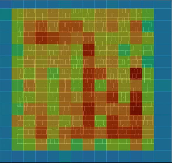
Final Congestion
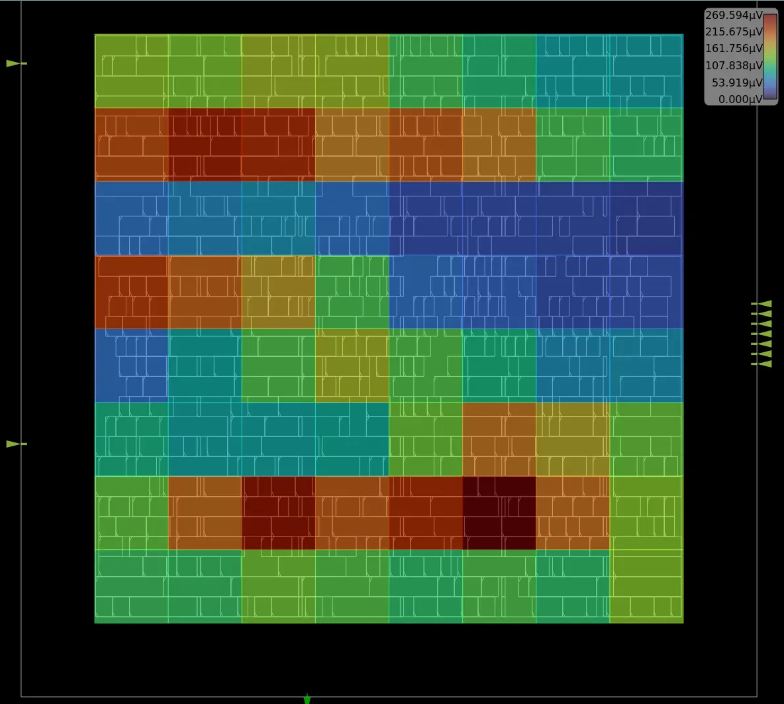
Final IR Drop
Viewing the Chip in KLayout
The 7 Button Diatonic Chord Monophonic Synthesizer ASIC
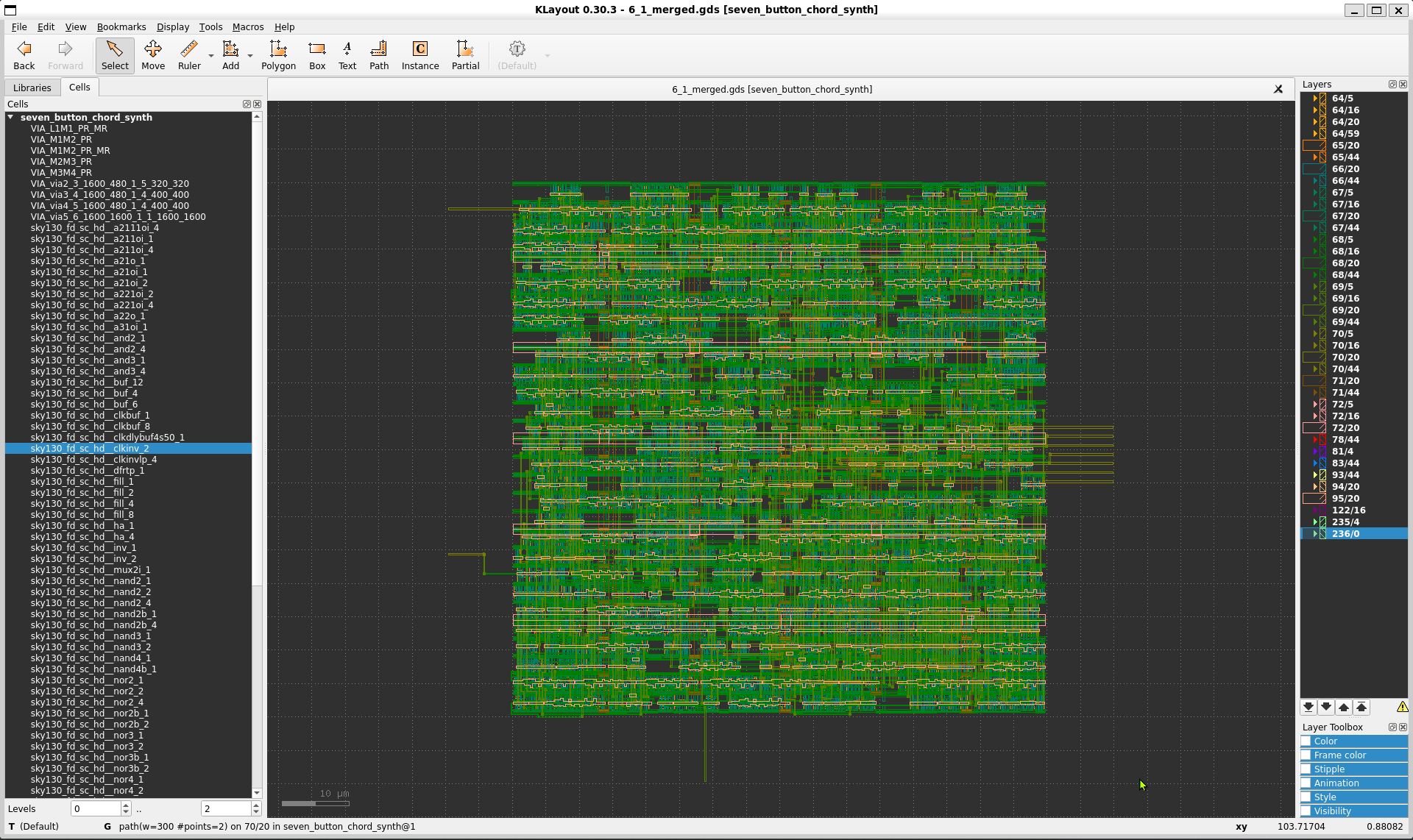
Now let’s break down this image…
(wip)
Learning with ChatGPT
I used ChatGPT extensively during this course to accelerate my learning. There was so much (difficult new topics) to learn in such a short period of time, and ChatGPT served as my personal tutor and advisor. To avoid “Chatty” simply doing my homework for me, I asked many supplementary questions and read all of the explanations throughout the process. And I learned a ton.
Reflection
Wow. I can hardly believe I actually got this far.
Definitely could not have succeeded without ChatGPT’s guidance and assistance, but I learned a ton going through the process methodically from beginning to end. I probably missed a few things required for class…but this is what I am able to manage for now.