Final Project > Deliverables
7 Button Diatonic Chord Mono Synth ASIC > Functionality
My chip design emulates the functionality of a commercial synthesizer called the HiChord,
…which produces 7 diatonic chords audio output from 7 buttons. Only one button can be pressed at a time (no sound generated with multiple buttons pressed). The audio output is a 1-bit square wave.
C major > C E G
D min > D F A
E min > E G B
F major > F A C
G major > G B D
A min > A C E
B dim > B D F
- The system clock input drives note divider logic
- Internal counters divide the clock to generate square-wave note tones (7 notes of 7 different frequencies in total)
- 3 notes are combined into a chord and outputted as audio
- The system resets to no sound when the button is released
The HiChord has a multitude of other functions such as pitch bend, waveform selection, octave selection, etc. which were not implemented in my design.
I focused only on sound generation from 7 button inputs.
The resulting chip design meets the requirements of sky130hd and Tiny Tapeout and should be fabricatable.
7 Button Diatonic Chord Mono Synth ASIC > Design Logic
The chip design features:
- 1x Clock INPUT
- 1x Reset INPUT
- 7x Button INPUTs
-
1x Audio OUTPUT Register
-
A Prescaler Logic Block was written to reduce the assumed 50MHz input clock signal down to 1MHz to make it possible to play notes from the 3rd and 4th registers of a piano with frequencies ranging from 131.81 Hz (C3) to 987.77 Hz (B5).
-
A 16-bit Counter was divided and utilized to generate square waves of different frequencies from C3 to B3, 130.81 Hz to 246.94 Hz.
-
A 7-bit Signal Wire was created to accept INPUT signals from 7 different buttons, each assigned to a specific note.
-
3 different Button Conditions were defined: exactly one pressed, more than one pressed and none pressed.
-
Verilog OR Reduction logic was applied to recognize which Button Condition is active.
-
A 16-bit register is utilized to store the 3 note values of the currently pressed chord key.
-
A long Conditional Statement is used to determine which key was pressed and which 3 notes should be sent to the Chord Register.
-
A 16-bit register is used to record counter and tone values.
-
Moore State Machine Logic is utilized generate and output chord audio.
7 Button Diatonic Chord Mono Synth ASIC > Verilog RTL Code
// 7-Button Diatonic Chord Monophonic Synthesizer Chip
// coded with ChatGPT assistance

module button_chord_7_optimized (
    input  clk,
    input  reset,

    //unique input for each of 7 chord button
    input  BTN_C,   // C major = C E G
    input  BTN_D,   // D minor = D F A
    input  BTN_E,   // E minor = E G B
    input  BTN_F,   // F major = F A C
    input  BTN_G,   // G major = G B D
    input  BTN_A,   // A minor = A C E
    input  BTN_B,   // B dim   = B D F

    output reg audio_out //assigned to always block
);

    // Clock Prescaler: 50 MHz -> 1 MHz
    reg [5:0] prescaler; //6-bit register
    reg audio_tick;

    // Prescaler Logic block
    always @(posedge clk or posedge reset) begin
        if (reset) begin
            prescaler  <= 6'd0;
            audio_tick <= 1'b0;
        end else begin
            if (prescaler == 6'd49) begin //count to 50
                prescaler  <= 6'd0;
                audio_tick <= 1'b1; //generate one audio tick
            end else begin
                prescaler  <= prescaler + 6'd1;
                audio_tick <= 1'b0;
            end
        end
    end

    // Prescaled Clock
    // divider = 1,000,000 / (2 * f_note)
    // generate 7 note frequencies
    localparam [15:0] C3_DIV = 16'd3822; // 130.81 Hz
    localparam [15:0] D3_DIV = 16'd3405; // 146.83 Hz
    localparam [15:0] E3_DIV = 16'd3034; // 164.81 Hz
    localparam [15:0] F3_DIV = 16'd2863; // 174.61 Hz
    localparam [15:0] G3_DIV = 16'd2551; // 196.00 Hz
    localparam [15:0] A3_DIV = 16'd2273; // 220.00 Hz
    localparam [15:0] B3_DIV = 16'd2025; // 246.94 Hz


    // Button handling
    // valid_chord = exactly one button is pressed
    wire [6:0] buttons; //7-bit signal line
    assign buttons = {BTN_C, BTN_D, BTN_E, BTN_F, BTN_G, BTN_A, BTN_B}; //assigns button names to each bit of the signal line (like an array) each to express a boolean value for pressed or unpressed

    // define signal lines
    wire any_pressed;
    wire more_than_one;
    wire valid_chord;

    // button press checks
    assign any_pressed    = |buttons; //verilog 'reduction OR', "is any button pressed?"
    assign more_than_one  = |(buttons & (buttons - 7'd1)); //"is more than one button pressed"
    assign valid_chord    = any_pressed & ~more_than_one; //"is only one button pressed?"

    // Selected divider values for currently active chord
    reg [15:0] div1, div2, div3;

    // Chord Selection Logic Block
    // Chord case states for each button
    always @(*) begin
        // default = silence
        div1 = 16'd0;
        div2 = 16'd0;
        div3 = 16'd0;

        if (valid_chord) begin
            if (BTN_C) begin
                // C major = C E G
                div1 = C3_DIV;
                div2 = E3_DIV;
                div3 = G3_DIV;
            end
            else if (BTN_D) begin
                // D minor = D F A
                div1 = D3_DIV;
                div2 = F3_DIV;
                div3 = A3_DIV;
            end
            else if (BTN_E) begin
                // E minor = E G B
                div1 = E3_DIV;
                div2 = G3_DIV;
                div3 = B3_DIV;
            end
            else if (BTN_F) begin
                // F major = F A C
                div1 = F3_DIV;
                div2 = A3_DIV;
                div3 = C3_DIV;
            end
            else if (BTN_G) begin
                // G major = G B D
                div1 = G3_DIV;
                div2 = B3_DIV;
                div3 = D3_DIV;
            end
            else if (BTN_A) begin
                // A minor = A C E
                div1 = A3_DIV;
                div2 = C3_DIV;
                div3 = E3_DIV;
            end
            else begin
                // BTN_B
                // B diminished = B D F
                div1 = B3_DIV;
                div2 = D3_DIV;
                div3 = F3_DIV;
            end
        end
    end

    // Three independent tone generators
    reg [15:0] counter1, counter2, counter3;
    reg tone1, tone2, tone3;

    // Tone Generator Logic Block
    always @(posedge clk or posedge reset) begin
        if (reset) begin
            counter1  <= 16'd0;
            counter2  <= 16'd0;
            counter3  <= 16'd0;
            tone1     <= 1'b0;
            tone2     <= 1'b0;
            tone3     <= 1'b0;
            audio_out <= 1'b0;
        end else begin
            if (valid_chord) begin
                if (audio_tick) begin
                    // tone 1
                    if (counter1 >= div1) begin
                        counter1 <= 16'd0;
                        tone1    <= ~tone1;
                    end else begin
                        counter1 <= counter1 + 16'd1;
                    end

                    // tone 2
                    if (counter2 >= div2) begin
                        counter2 <= 16'd0;
                        tone2    <= ~tone2;
                    end else begin
                        counter2 <= counter2 + 16'd1;
                    end

                    // tone 3
                    if (counter3 >= div3) begin
                        counter3 <= 16'd0;
                        tone3    <= ~tone3;
                    end else begin
                        counter3 <= counter3 + 16'd1;
                    end

                    // Chord Output
                    audio_out <= tone1 ^ tone2 ^ tone3;
                end
            end else begin
                // silence if zero or multiple buttons are pressed
                counter1  <= 16'd0;
                counter2  <= 16'd0;
                counter3  <= 16'd0;
                tone1     <= 1'b0;
                tone2     <= 1'b0;
                tone3     <= 1'b0;
                audio_out <= 1'b0;
            end
        end
    end

endmodule
7 Button Diatonic Chord Mono Synth ASIC > Testbench Code
// 7 Button Chord Synth Testbench
`timescale 1ns/1ps
module testbench;
reg clk;
reg reset;
reg BTN_C;
reg BTN_D;
reg BTN_E;
reg BTN_F;
reg BTN_G;
reg BTN_A;
reg BTN_B;
wire audio_out;
// Instantiate your synth
seven_button_chord_synth uut (
.clk(clk),
.reset(reset),
.BTN_C(BTN_C),
.BTN_D(BTN_D),
.BTN_E(BTN_E),
.BTN_F(BTN_F),
.BTN_G(BTN_G),
.BTN_A(BTN_A),
.BTN_B(BTN_B),
.audio_out(audio_out)
);
// clock generator
always #10 clk = ~clk;
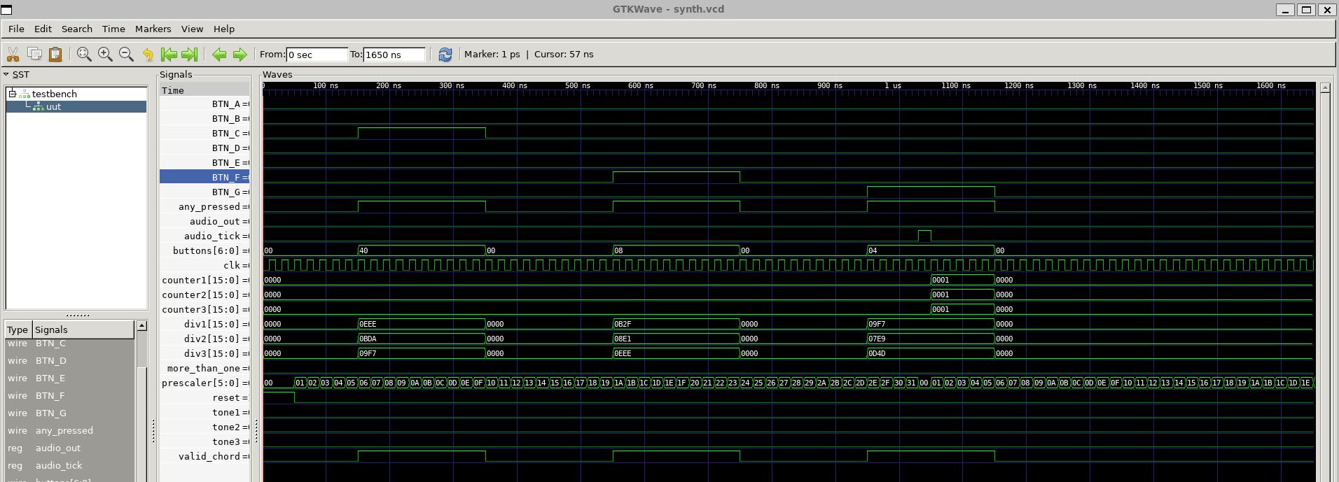
initial begin
$dumpfile("synth.vcd"); // waveform file
$dumpvars(0,testbench);
clk = 0;
reset = 1;
BTN_C=0; BTN_D=0; BTN_E=0;
BTN_F=0; BTN_G=0; BTN_A=0; BTN_B=0;
#50 reset = 0;
// press C chord
#100 BTN_C = 1;
#200 BTN_C = 0;
// press F chord
#200 BTN_F = 1;
#200 BTN_F = 0;
// press G chord
#200 BTN_G = 1;
#200 BTN_G = 0;
#500 $finish;
end
endmodule
7 Button Diatonic Chord Mono Synth ASIC > Production Workflow
The full toolchain necessary to process the Verilog RTL code to generate a fabricatable GDS file was installed in a Windows Subsystem Linux (WSL) Ubuntu 22.04 environment. The workflow and software utilized were as follows:
From design to ASIC fabrication:
-
Conceptualize the Functionality of a Small Chip Design
- Answer > What do I want the chip to do?
- ex: “Blink and LED when a button is pushed”
- Make a functionality flow diagram
-
Write Verilog RTL Code
- Describe the conceptual functionality as data-level (RTL) code descriptions
- Use Icarus-Verilog
-
Simulate the design
- Test the RTL code in simulation to ensure the functionality works as expected
- Use Icarus-Verilog
-
View simulation waveforms
- Review waveforms generated by the simulation to confirm correct functionality
- Use GTKwave
-
Synthesize RTL into Gate Level representation
- Convert RTL code into a gate-level description of the hardware circuit
- Use Yosys
-
Place & Route connection
- Define physical connections between gates and output GDS file
- Use OpenRoad
-
Inspect Layout
- Review chip design physical layout for errors
- Use KLayout
-
Send GDS to Chip Foundry for Fabrication
Reports & Files
Reports:
- Floor Plan
- Detailed Place
- Global Place
- Resizer
- CTS Final
- Glogal Route
- Route DRC
- Finish
GDS:
- 7_button_chord_synth.gds
7 Button Diatonic Chord Mono Synth ASIC > Logic:
7 Button Diatonic Chord Mono Synth ASIC > Waveforms
7 Button Diatonic Chord Mono Synth ASIC > Features:
Chip Area: ~4800 sq. microns
Area Utilization: 77%
450 logic cells
59 Flip-Flops
11 Clocks
7 Inputs
Cells:
50% Sequential
8.8% Combinational
41.2% Clock
Power:
2.17 mW Power Req’t
0.954 mW Sequential
0.13 mW Combinational
1.09 mW Clock
Finish Critical Path Delay > 2.6057
Finish Critical Path Slack > 0.1244
Fmax > 420 MHz
7 Button Diatonic Chord Mono Synth ASIC > Chip Images
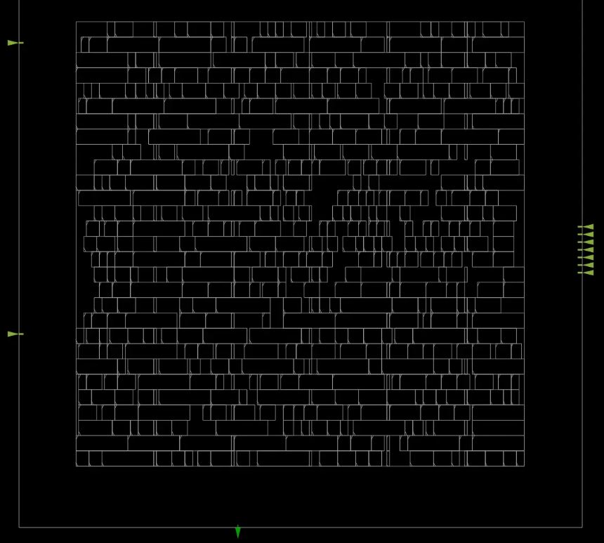
Final Placement
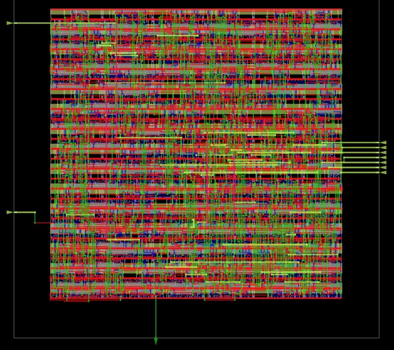
Final Routing
Final Clock
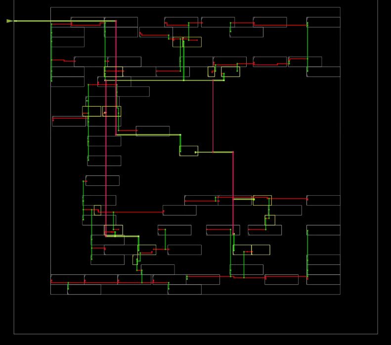
Final Worst Path
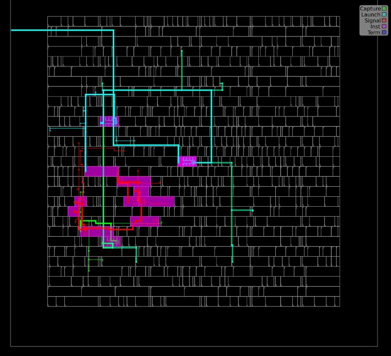
Final Congestion
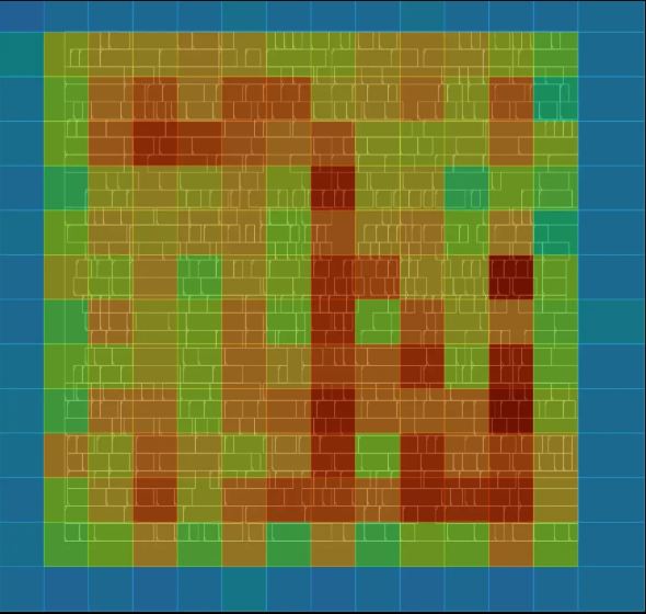
Final IR Drop