Final Project > Development
Synthesizer Chip Development
Moore State Machine > Button-LED State Machine
For the Session 5 assignment homework, I learned about the Moore State Machine and learned to use Verilog to write code that described state transition logic as case statements. Depending on the case state, a different output would be registered.
The Moore State Machine had 3 primary function blocks:
- State Register > stores the Current State.
- Next-State Logic > decides what the next state will be
- Output Logic > generate output outcomes
I used that learning to write a small functionality description of a button press turning on an LED. The LED ON/OFF condition depended on state not inputs directly. The following is the Button-LED State Machine code with a slight modification to add the edge case of both buttons being pushed (to trigger a reset state).
// Button-LED State Machine

module hello_world_FSM(
    input clk,
    input reset,
    input ON,
    input OFF,
    output reg led
);

reg state;

localparam OFF_STATE = 0; //define a variable for the OFF state
localparam ON_STATE  = 1; //define a variable for the ON state

always @(posedge clk or posedge reset) begin
    if (reset)
        state <= OFF_STATE;

    else begin
        case(state)

            OFF_STATE:
                if (ON & OFF) //2 button reset
                    state <= OFF_STATE;
                else if (ON)
                    state <= ON_STATE;

            ON_STATE:
                if (ON & OFF)  //2 button reset
                    state <= OFF_STATE;
                else if (OFF)
                    state <= OFF_STATE;

        endcase
    end
end

always @(*) begin
    case(state)
        OFF_STATE: led = 0;
        ON_STATE:  led = 1;
    endcase
end

endmodule
Button Press Tone Generator
If I could turn on an LED with a button press, I thought that I could also output a Square Wave tone with a button press. So first I had to learn how to generate a Square Wave tone. ChatGPT to the rescue, producing the following Square Wave Tone Generator code.
module tone_generator (
    input  clk,
    input  reset,
    output reg audio_out //output from always block must be declared as a register
);

reg [15:0] counter; //16-bit counter...stores values 0 up to 65535

//block runs when either clock signal rises or resets when reset signal rises
always @(posedge clk or posedge reset) begin
    if (reset) begin
        counter    <= 16'd0;
        audio_out  <= 1'b0;
    end else begin
        if (counter == 16'd24999) begin
            counter   <= 16'd0;
            audio_out <= ~audio_out;
        end else begin
            counter <= counter + 16'd1;
        end
    end
end

endmodule
I analyzed the code and have the following understanding:
- A module is created with the name Tone Generator
- 2 INPUTs (Clock and Reset) and 1 OUTPUT (audio_out register) is defined for the module
- A 16-bit register called ‘counter’ is defined
- An always@ block is defined timed on the rising edge of the clock or reset signals
- A conditional statement for reset functionality writes counter and audio_out to zero if triggered.
- A non-reset conditional action statement:
- If the counter counts has reached the trigger value 25000
- Resets the counter back to 0 (to count up to 24999 again)
- Register a the inverse digital value to what is currently in the audio_out register (0 to 1 and 1 to 0)
- if the counter has not yet reached the value 25000
- add increment the counter value by 1
The chip…
- takes in a clock signal
- counts clock cycles
- flips the output after a fixed number of cycles
- …the periodic output reversal generates a square wave signal
The key point for this code is the counter trigger value. This value will eventually become the frequency or note that is outputted as an audio signal. BUT!!!…this value is NOT the frequency value itself. The resulting chip from this Verilog code will depend on an external clock, and this clock frequency will determine the final output audio frequency. For example, assuming an incoming clock frequency of 50MHz, the audio frequency would be 1kHz (1000Hz = 50MHz/(2 * 25,000)). If the incoming clock frequency is different, a different note would be generated. So…the chip would have to be designed with a specific external clock frequency in mind, to have the output note be the desired frequency.
Now to combine the Button-LED and the Square Wave Tone Generator into a Button-Tone State Machine.
//Button-Tone State Machine

module hello_world_FSM(
    input  clk,
    input  reset,
    input  ON,
    input  OFF,
    output reg audio_out
);

reg state;
reg [15:0] counter;

localparam OFF_STATE = 1'b0;
localparam ON_STATE  = 1'b1;

// adjust this value depending on external clock frequency
// for 50 MHz external clock: 24999 gives about 1 kHz tone
// middle C is 261.6256
localparam Wave_Freq = 16'd24999;

//State Transition
always @(posedge clk or posedge reset) begin
    if (reset) begin
        state <= OFF_STATE;
    end else begin
        case (state)

            OFF_STATE:
                if (ON & OFF)        // 2-button reset
                    state <= OFF_STATE;
                else if (ON)
                    state <= ON_STATE;

            ON_STATE:
                if (ON & OFF)        // 2-button reset
                    state <= OFF_STATE;
                else if (OFF)
                    state <= OFF_STATE;

            default:
                state <= OFF_STATE;

        endcase
    end
end

// Tone generator
always @(posedge clk or posedge reset) begin
    if (reset) begin //checks if reset buttons pressed
        counter   <= 16'd0;
        audio_out <= 1'b0;
    end else begin //if no reset
        if (state == ON_STATE) begin //if ON button pressed
            if (counter == Wave_Freq) begin //start counter, run the tone generator
                counter   <= 16'd0; //counter resets back to 0
                audio_out <= ~audio_out; //if tone OFF, turn ON and vice versa...continues ON/OFF until button released
            end else begin
                counter <= counter + 16'd1; //increment counter by 1
            end
        end else begin //when button not pressed
            counter   <= 16'd0; //counter reset to 0
            audio_out <= 1'b0; //audio output stops
        end
    end
end

endmodule
Button-Chord State Machine
A final project idea is forming…
Now I want to see if a button press can generate a chord instead of a single tone. I asked ChatGPT for assistance and its response is as follows:
- A single tone uses one counter and generates one square wave output
- A chord requires multiple counters to generate multiple square waves…that are combined into a single audio_out.
The change in the code from single tone to chord involves:
- Setting different counter lengths for the different notes of the chord.
// f_out = clk / (2 * divider)
// assume a 50MHz clock
localparam C5_DIV = 16'd47778; // ~523.3 Hz
localparam E5_DIV = 16'd37922; // ~659.3 Hz
localparam G5_DIV = 16'd31888; // ~784.0 Hz
- Adding more counters and tone variables in the State Transfer Logic block
// the reset condition
always @(posedge clk or posedge reset) begin
    if (reset) begin
        counter1   <= 16'd0;
        counter2   <= 16'd0;
        counter3   <= 16'd0;
        tone1      <= 1'b0;
        tone2      <= 1'b0;
        tone3      <= 1'b0;
        audio_out  <= 1'b0;
    end
- Writing tone generating conditionals for each of the 3 notes of the chord
// the non-reset action condition
if (state == ON_STATE) begin
    // Tone 1: C4 case
    if (counter1 == C5_DIV) begin
        counter1 <= 16'd0; // reset counter
        tone1    <= ~tone1; // output C4 tone
    end else begin
        counter1 <= counter1 + 16'd1; // increment counter
    end

    // Tone 2: E4 case
    if (counter2 == E5_DIV) begin
        counter2 <= 16'd0; // reset counter
        tone2    <= ~tone2; // output E4 tone
    end else begin
        counter2 <= counter2 + 16'd1; // increment counter
    end

    // Tone 3: G4 case
    if (counter3 == G5_DIV) begin
        counter3 <= 16'd0; // reset counter
        tone3    <= ~tone3; // output G4 tone
    end else begin
        counter3 <= counter3 + 16'd1; // increment counter
    end
Individual tones are combined into a single audio_out note output using bitwise XORs.
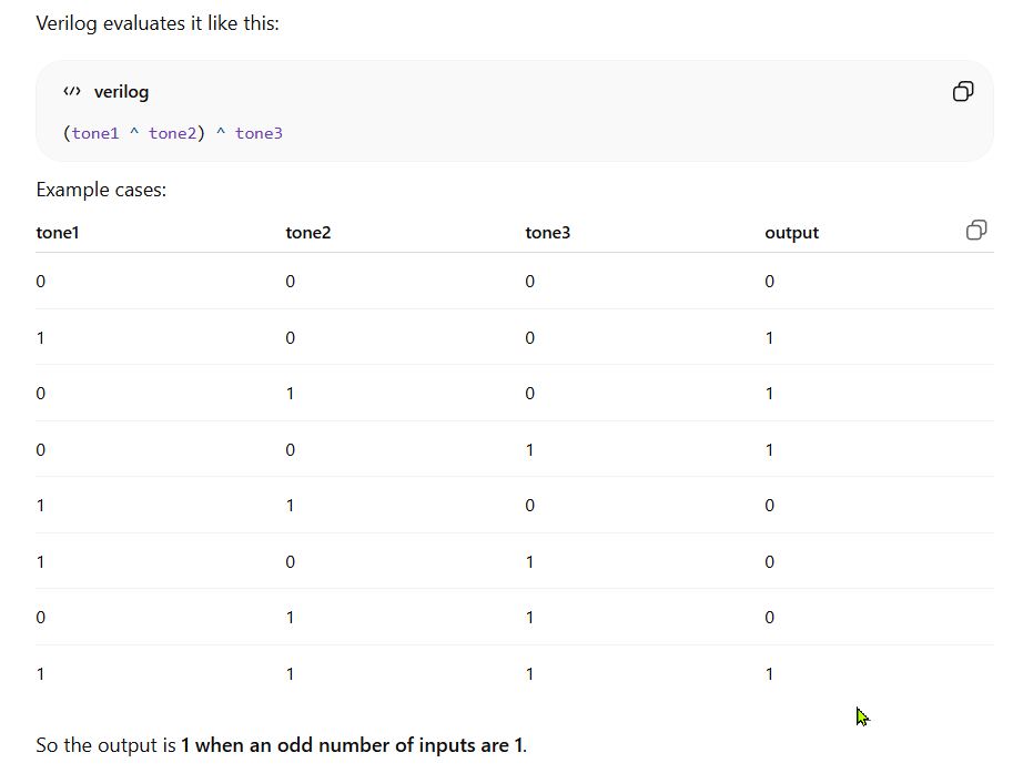
Represented in code as…((tone^tone2)^tone3)
The full Button-Chord code (ChatGPT)
//Button-Chord State Machine

module button_chord_FSM (
    input  clk,
    input  reset,
    input  ON,
    input  OFF,
    output reg audio_out
);

    reg state;

    localparam OFF_STATE = 1'b0;
    localparam ON_STATE  = 1'b1;

    // State machine
    always @(posedge clk or posedge reset) begin
        if (reset)
            state <= OFF_STATE;
        else begin
            case (state)
                OFF_STATE: begin
                    if (ON)
                        state <= ON_STATE;
                    else
                        state <= OFF_STATE;
                end

                ON_STATE: begin
                    if (OFF)
                        state <= OFF_STATE;
                    else
                        state <= ON_STATE;
                end
            endcase
        end
    end

    // Chord generator section

    reg [15:0] counter1, counter2, counter3;
    reg tone1, tone2, tone3;

    // Asssuming a 50 MHz clock
    // f_out = clk / (2 * divider)
    // c-major chord

    localparam C4_DIV = 16'd95556; // ~261.6 Hz
    localparam E4_DIV = 16'd75843; // ~329.6 Hz
    localparam G4_DIV = 16'd63776; // ~392.0 Hz

    always @(posedge clk or posedge reset) begin
        if (reset) begin
            counter1   <= 16'd0;
            counter2   <= 16'd0;
            counter3   <= 16'd0;
            tone1      <= 1'b0;
            tone2      <= 1'b0;
            tone3      <= 1'b0;
            audio_out  <= 1'b0;
        end
        else begin
            if (state == ON_STATE) begin
                // Tone 1: C4 case
                if (counter1 == C5_DIV) begin
                    counter1 <= 16'd0; // reset counter
                    tone1    <= ~tone1; // output C4 tone
                end else begin
                    counter1 <= counter1 + 16'd1; // increment counter
                end

                // Tone 2: E4 case
                if (counter2 == E5_DIV) begin
                    counter2 <= 16'd0; // reset counter
                    tone2    <= ~tone2; // output E4 tone
                end else begin
                    counter2 <= counter2 + 16'd1; // increment counter
                end

                // Tone 3: G4 case
                if (counter3 == G5_DIV) begin
                    counter3 <= 16'd0; // reset counter
                    tone3    <= ~tone3; // output G4 tone
                end else begin
                    counter3 <= counter3 + 16'd1; // increment counter
                end

                // Combine the three square waves into one 1-bit chord output with XOR's
                // Previous values of tone1, tone2, tone3 from the last clock edge
                audio_out <= tone1 ^ tone2 ^ tone3;

            end
            else begin
                counter1   <= 16'd0;
                counter2   <= 16'd0;
                counter3   <= 16'd0;
                tone1      <= 1'b0;
                tone2      <= 1'b0;
                tone3      <= 1'b0;
                audio_out  <= 1'b0;
            end
        end
    end

endmodule
Adding a Prescaler
A ChatGPT recommendation. Reduce the clock signal to a lower frequency, to allow lower note frequencies to be calculated and fit within the counter bit size. Currently the 4th note register cannot be played without increasing the counter bit size (the values calculated are larger than 65535 possible with 16-bit).
Reduce incoming 50MHz clock signal to 1MHz, allowing the use of 16-bit tone generators.
// Prescaler: 50MHZ to 1MHz
// for every 50 ticks on the 50MHz clock, generate 1 audio clock tick
reg [5:0] prescaler; //6-bit counter
reg audio_tick; //register for prescaled clock

always @(posedge clk or posedge reset) begin
    if (reset) begin
        prescaler <= 6'd0;
        slow_tick <= 1'b0;
    end else begin
        if (prescaler == 6'd49) begin //counts to 50
            prescaler <= 6'd0; //reset prescaler count
            audio_tick <= 1'b1; //generate 1 audio clock tick
        end else begin
            prescaler <= prescaler + 6'd1; //increment prescaler clock by 1
            audio_tick <= 1'b0; //reset audio clock
        end
    end
end
And the full code…
// Button-Chord State Machine - Clock Prescaler
module button_chord_FSM (
    input  clk,
    input  reset,
    input  ON,
    input  OFF,
    output reg audio_out
);

    //==================================================
    // State machine
    //==================================================
    reg state;

    localparam OFF_STATE = 1'b0;
    localparam ON_STATE  = 1'b1;

    always @(posedge clk or posedge reset) begin
        if (reset)
            state <= OFF_STATE;
        else begin
            case (state)
                OFF_STATE: begin
                    if (ON)
                        state <= ON_STATE;
                    else
                        state <= OFF_STATE;
                end

                ON_STATE: begin
                    if (OFF)
                        state <= OFF_STATE;
                    else
                        state <= ON_STATE;
                end
            endcase
        end
    end

    //==================================================
    // Prescaler: 50 MHz -> 1 MHz tick
    // 50 clock cycles of 50 MHz = 1 us
    // so make a pulse every 50 cycles
    //==================================================
    reg [5:0] prescaler;
    reg audio_tick;

    always @(posedge clk or posedge reset) begin
        if (reset) begin
            prescaler  <= 6'd0;
            audio_tick <= 1'b0;
        end else begin
            if (prescaler == 6'd49) begin
                prescaler  <= 6'd0;
                audio_tick <= 1'b1;   // one-clock pulse
            end else begin
                prescaler  <= prescaler + 6'd1;
                audio_tick <= 1'b0;
            end
        end
    end

    //==================================================
    // Chord generator
    // Using 1 MHz tick so 16-bit counters are enough
    //
    // divider = 1,000,000 / (2 * f_note)
    //
    // C3 = 130.81 Hz -> ~3822
    // E3 = 164.81 Hz -> ~3034
    // G3 = 196.00 Hz -> ~2551
    //==================================================
    reg [15:0] counter1, counter2, counter3;
    reg tone1, tone2, tone3;

    localparam [15:0] C3_DIV = 16'd3822;
    localparam [15:0] E3_DIV = 16'd3034;
    localparam [15:0] G3_DIV = 16'd2551;

    always @(posedge clk or posedge reset) begin
        if (reset) begin
            counter1  <= 16'd0;
            counter2  <= 16'd0;
            counter3  <= 16'd0;
            tone1     <= 1'b0;
            tone2     <= 1'b0;
            tone3     <= 1'b0;
            audio_out <= 1'b0;
        end else begin
            if (state == ON_STATE) begin

                if (audio_tick) begin
                    // Tone 1: C3
                    if (counter1 == C3_DIV) begin
                        counter1 <= 16'd0;
                        tone1    <= ~tone1;
                    end else begin
                        counter1 <= counter1 + 16'd1;
                    end

                    // Tone 2: E3
                    if (counter2 == E3_DIV) begin
                        counter2 <= 16'd0;
                        tone2    <= ~tone2;
                    end else begin
                        counter2 <= counter2 + 16'd1;
                    end

                    // Tone 3: G3
                    if (counter3 == G3_DIV) begin
                        counter3 <= 16'd0;
                        tone3    <= ~tone3;
                    end else begin
                        counter3 <= counter3 + 16'd1;
                    end

                    // combine square waves
                    audio_out <= tone1 ^ tone2 ^ tone3;
                end
            end else begin
                counter1  <= 16'd0;
                counter2  <= 16'd0;
                counter3  <= 16'd0;
                tone1     <= 1'b0;
                tone2     <= 1'b0;
                tone3     <= 1'b0;
                audio_out <= 1'b0;
            end
        end
    end

endmodule
Sound Quality Limitation:
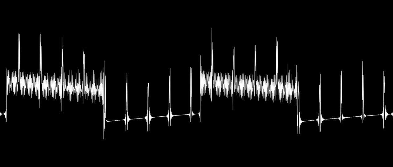
- Because audio_out is only 1-bit, the chord quality will be low > a digital composite waveform
PWM audio would be needed to create a better chord audio output
Scanning the internet I found this example of 1-bit sound. I kinda like the ‘retro’ sound of it. Besides, adding PWM Audio in my RTL may bloat the cell count too much. And you gotta love the waveform it generates. Look at all those harmonics!
Conclusion
With all the ChatGPT explorations, I think I have learned enough and collected enough knowledge components to be able to work on my final project idea > 7 Button Diatonic Chord Synth
Possible Future Additions
- UART can function as a Sequencer
- PWM to improve sound quality