Session 5: RTL Design & Verification

Summary
RTL = Registers + Combinational Logic + Clock
Use wire + assign for combinational logic
Use reg + always @(posedge clk) for sequential logic
FSMs organize sequential behavior
Testbenches verify your design before synthesis
Homework
- Write Verilog for your project’s core module (aim for 10-30 lines to start)
- Integrate with any provided library modules (debounce, UART) — create a top-level wrapper
- Simulate with a testbench and examine waveforms in GTKWave
- Run linter (
verilator --lint-only) and fix any warnings
Assignment 1 — Write Verilog for the core module
My project is the APOLLO-4G a 4-bit CPU inspired by the Intel 4004 from 1971. The core module is the ALU (Arithmetic Logic Unit), which supports 5 operations: ADD, SUB, AND, OR, and XOR.
I created the project folder inside the container:
cd /foss/designs
mkdir mini_cpu
cd mini_cpu
Since writing Verilog directly in the terminal editor was slow, I used Python to generate the files directly:
python3 << 'PYEOF'
lines = [
    "`timescale 1ns/1ps",
    "",
    "module alu (",
    "    input  wire [3:0] a,",
    "    input  wire [3:0] b,",
    "    input  wire [2:0] op,",
    "    output reg  [3:0] result,",
    "    output reg        zero,",
    "    output reg        carry",
    ");",
    "    always @(*) begin",
    "        carry = 1'b0;",
    "        case (op)",
    "            3'b000: {carry, result} = a + b;",
    "            3'b001: {carry, result} = a - b;",
    "            3'b010: result = a & b;",
    "            3'b011: result = a | b;",
    "            3'b100: result = a ^ b;",
    "            default: result = 4'b0;",
    "        endcase",
    "        zero = (result == 4'b0);",
    "    end",
    "endmodule"
]
with open('/foss/designs/mini_cpu/alu.v', 'w') as f:
    f.write('\n'.join(lines))
print('alu.v creado!')
PYEOF
alu.v
`timescale 1ns/1ps

module alu (
    input  wire [3:0] a,
    input  wire [3:0] b,
    input  wire [2:0] op,
    output reg  [3:0] result,
    output reg        zero,
    output reg        carry
);
    // Opcodes
    // 000 = ADD
    // 001 = SUB
    // 010 = AND
    // 011 = OR
    // 100 = XOR

    always @(*) begin
        carry = 1'b0;
        case (op)
            3'b000: {carry, result} = a + b;
            3'b001: {carry, result} = a - b;
            3'b010: result = a & b;
            3'b011: result = a | b;
            3'b100: result = a ^ b;
            default: result = 4'b0;
        endcase
        zero = (result == 4'b0);
    end

endmodule
Assignment 2 — Integrate with Debounce and UART
I created the debounce and UART modules, then connected everything in a top-level wrapper.
debounce.v
`timescale 1ns/1ps

module debounce (
    input  wire clk,
    input  wire rst_n,
    input  wire noisy_in,
    output reg  clean_out
);
    reg [19:0] count;
    reg sync_0, sync_1;

    always @(posedge clk or negedge rst_n) begin
        if (!rst_n) begin
            sync_0 <= 1'b0; sync_1 <= 1'b0;
            count  <= 20'd0; clean_out <= 1'b0;
        end else begin
            sync_0 <= noisy_in;
            sync_1 <= sync_0;
            if (sync_1 == clean_out)
                count <= 20'd0;
            else if (count >= 20'd500000) begin
                clean_out <= sync_1;
                count <= 20'd0;
            end else
                count <= count + 1'b1;
        end
    end
endmodule
uart_tx.v
`timescale 1ns/1ps

module uart_tx (
    input  wire       clk,
    input  wire       rst_n,
    input  wire       start,
    input  wire [7:0] data,
    output reg        tx,
    output reg        busy
);
    localparam CLKS_PER_BIT = 434; // 50MHz / 115200 baud

    reg [9:0]  shift_reg;
    reg [9:0]  bit_cnt;
    reg [3:0]  bit_idx;

    always @(posedge clk or negedge rst_n) begin
        if (!rst_n) begin
            tx <= 1'b1; busy <= 1'b0;
            shift_reg <= 10'h3FF; bit_cnt <= 0; bit_idx <= 0;
        end else if (!busy && start) begin
            shift_reg <= {1'b1, data, 1'b0};
            bit_cnt <= 0; bit_idx <= 0; busy <= 1'b1;
        end else if (busy) begin
            if (bit_cnt < CLKS_PER_BIT - 1)
                bit_cnt <= bit_cnt + 1;
            else begin
                bit_cnt <= 0;
                tx <= shift_reg[bit_idx];
                bit_idx <= bit_idx + 1;
                if (bit_idx == 9) busy <= 1'b0;
            end
        end
    end
endmodule
top.v
`timescale 1ns/1ps

module top (
    input  wire       clk,
    input  wire       rst_n,
    input  wire       btn_op_up,
    input  wire       btn_op_down,
    input  wire [3:0] a,
    input  wire [3:0] b,
    output wire       tx,
    output reg  [3:0] result,
    output reg        zero,
    output reg        carry
);
    wire clean_up, clean_down;
    reg  [2:0] op;

    debounce u_deb_up (
        .clk(clk), .rst_n(rst_n),
        .noisy_in(btn_op_up), .clean_out(clean_up)
    );
    debounce u_deb_down (
        .clk(clk), .rst_n(rst_n),
        .noisy_in(btn_op_down), .clean_out(clean_down)
    );

    wire [3:0] alu_result;
    wire       alu_zero, alu_carry;

    alu u_alu (
        .a(a), .b(b), .op(op),
        .result(alu_result),
        .zero(alu_zero), .carry(alu_carry)
    );

    wire uart_busy;
    uart_tx u_uart (
        .clk(clk), .rst_n(rst_n),
        .start(clean_up | clean_down),
        .data({4'b0, alu_result}),
        .tx(tx), .busy(uart_busy)
    );

    always @(posedge clk or negedge rst_n) begin
        if (!rst_n) begin
            op <= 3'b000; result <= 4'b0;
            zero <= 1'b0; carry <= 1'b0;
        end else begin
            if (clean_up && op < 3'b100) op <= op + 1'b1;
            else if (clean_down && op > 3'b000) op <= op - 1'b1;
            result <= alu_result;
            zero   <= alu_zero;
            carry  <= alu_carry;
        end
    end

endmodule
Assignment 3 — Testbench and GTKWave
I needed a testbench to verify the ALU. I first tried creating the file manually, but it had syntax issues. The clean approach was to generate it with Python:
python3 << 'PYEOF'
lines = [
    "`timescale 1ns/1ps",
    "",
    "module alu_tb;",
    "    reg  [3:0] a, b;",
    "    reg  [2:0] op;",
    "    wire [3:0] result;",
    "    wire       zero, carry;",
    "",
    "    alu dut (",
    "        .a(a), .b(b), .op(op),",
    "        .result(result),",
    "        .zero(zero),",
    "        .carry(carry)",
    "    );",
    "",
    "    initial begin",
    "        $dumpfile(\"alu_tb.vcd\");",
    "        $dumpvars(0, alu_tb);",
    "        a = 4'd3; b = 4'd5; op = 3'b000; #1;",
    "        $display(\"ADD 3+5=%0d zero=%0d carry=%0d\", result, zero, carry);",
    "        a = 4'd8; b = 4'd3; op = 3'b001; #1;",
    "        $display(\"SUB 8-3=%0d zero=%0d carry=%0d\", result, zero, carry);",
    "        a = 4'd5; b = 4'd5; op = 3'b001; #1;",
    "        $display(\"SUB 5-5=%0d zero=%0d carry=%0d\", result, zero, carry);",
    "        a = 4'b1100; b = 4'b1010; op = 3'b010; #1;",
    "        $display(\"AND=%0b zero=%0d carry=%0d\", result, zero, carry);",
    "        a = 4'b1100; b = 4'b1010; op = 3'b011; #1;",
    "        $display(\"OR=%0b zero=%0d carry=%0d\", result, zero, carry);",
    "        a = 4'b1100; b = 4'b1010; op = 3'b100; #1;",
    "        $display(\"XOR=%0b zero=%0d carry=%0d\", result, zero, carry);",
    "        $finish;",
    "    end",
    "",
    "endmodule"
]
with open('/foss/designs/mini_cpu/alu_tb.v', 'w') as f:
    f.write('\n'.join(lines))
print('Archivo creado!')
PYEOF
Compiling and running the simulation:
iverilog -o alu_sim alu.v alu_tb.v
vvp alu_sim
Result:
VCD info: dumpfile alu_tb.vcd opened for output.
ADD 3+5=8  zero=0 carry=0
SUB 8-3=5  zero=0 carry=0
SUB 5-5=0  zero=1 carry=0
AND=1000   zero=0 carry=0
OR=1110    zero=0 carry=0
XOR=110    zero=0 carry=0
alu_tb.v:31: $finish called at 6000 (1ps)
All 5 operations pass! ✅
Opening GTKWave:
gtkwave alu_tb.vcd &
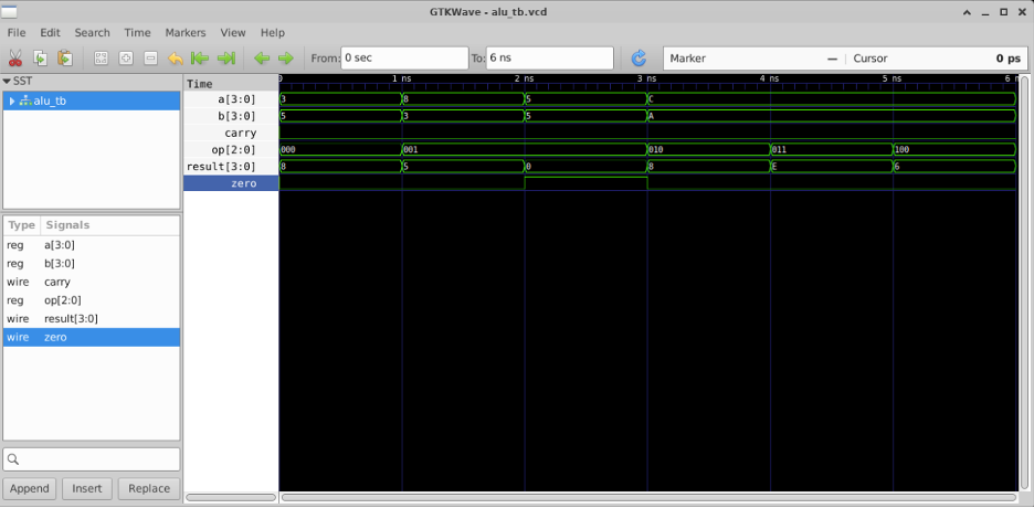
The waveform shows each operation updating result, zero, and carry correctly at every timestep.
Assignment 4 — Linter
I ran the Verilator linter to catch any potential warnings before synthesis:
verilator --lint-only -Wall alu.v alu_tb.v
Result:
- V e r i l a t i o n   R e p o r t: Verilator 5.044 2026-01-01 rev v5.044
- Verilator: Built from 0.046 MB sources in 3 modules, into 0.017 MB in 3 C++ files needing 0.000 MB
- Verilator: Walltime 0.006 s (elab=0.001, cvt=0.002, bld=0.000); cpu 0.005 s on 1 threads; alloced 28.828 MB
0 warnings, 0 errors. ✅
During development, I encountered several warnings from the linter related to unused signals (UNUSEDSIGNAL) and unconnected pins (PINCONNECTEMPTY) in the top-level module. For example:
%Warning-UNUSEDSIGNAL: top.v:23:16: Bits of signal are not used: 'pc'[3:2]
%Warning-UNUSEDSIGNAL: top.v:59:16: Signal is not used: 'reg_a'
%Warning-PINCONNECTEMPTY: top.v:77:10: Instance pin connected by name with empty reference: 'busy'
These were fixed by either using the signals properly or suppressing them with lint directives:
/* verilator lint_off UNUSEDSIGNAL */
wire [3:0] pc_full;
/* verilator lint_on UNUSEDSIGNAL */
After all fixes the linter returned 0 warnings. This is important any linter warning can become a real hardware bug after synthesis.
Tools Used
| Tool | Purpose |
|---|---|
| iverilog | Compile Verilog files |
| vvp | Run the compiled simulation |
| GTKWave | Visualize waveforms from VCD file |
| Verilator | Lint checker — finds potential bugs before synthesis |
| Python | Generate Verilog files cleanly from the terminal |